Rear starter setup
Rear starter setup
created November 26, 2000, updated March, 2007 (added link to new 3100cc "Phoenix" engine )
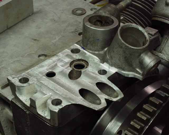
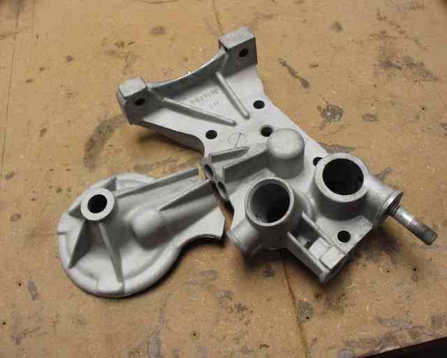
My first thought on a dynamo mount is shown below. I had the local machine shop flatten what WAS the oil cooler mount so that a bracket could be mounted on top of it. The remotely mounted oil cooler and filter hose connections would be located here and stick out the top in the form of 90 degree AN fittings, after the starter bracket was welded to this piece. This would make leaks easy to spot. All extra holes would be welded up internally to prevent oil from seeping around anywhere. This is a very high pressure area for oil.
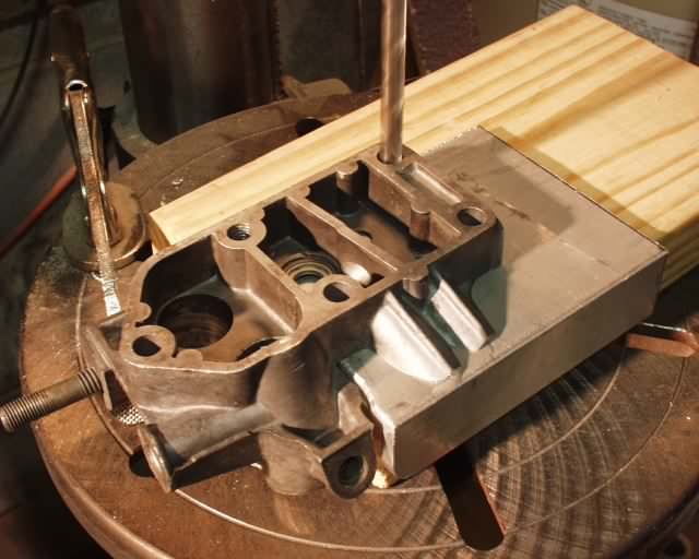
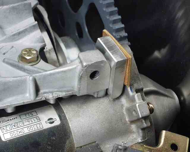
Then I cut a 6" length of 4x4 1/4" thick aluminum angle and epoxied it to the bracket temporarily, so I could match drill the holes. This is the upper starter bracket. I'll have it welded all the way around to make it permanent. There's a guy at work that's certified to weld on Shuttle rocket motor nozzles, who can probably handle this.
This setup allowed the retention of the oil cooler bypass valve, but obviously deleted the one for the filter. Now the cooler bypass valve would work for both cooler and filter. Total weight of this whole starter bracket setup was pretty minimal. This bracket was 8.7 ounces.
The method above was discarded before it ever flew, mainly because it's very difficult to weld the 40 year old cast 356 aluminum to the 6061-T6 plate. Anything that's been attached to an engine for 40 years will have absorbed a lot of oil, and while welding, the oil vaporizes, creating voids that are just about impossible to prevent or repair. On top of this, there are a lot of tight places to weld, which makes it even worse. So I moved on to a modified stock top plate, with only an alternator bracket welded to it. This worked fine (and is shown further down the page).
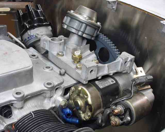
This is a Nissan Sentra starter and flex plate from a '96 model, although I think it's the same for all of them except for the rare 2.0 liter. The starter weighs just 5.5 pounds, while the flex plate is only 3 pounds. Starter body diameter is only 2.75 inches, and flexplate diameter is 10.75". Despite the flimsy appearance, the starter is very solidly mounted.
Obviously the oil cooler connection at the block will need to be blocked off. There is room for a plate to be fastened over the holes. There is about 3/4" of clearance between the 94mm cylinders and the rear of the starter, but there will be shrouding between the two. The alternator will fit out near the head, mounted in a manner similar to William's. Since it's a dynamo and will run in either direction, it could go on either side, but the pilot's side has more room due to the more forward location of that head. Due to the position of the starter I'll either need an idler pulley (which is heavy and something else to fail) or machine a belt groove into the flexplate adapter, which is what I think I'm going to do. First I'll figure out what diameter it needs to be to get 20 amps out of it at 3400 rpm, so a trip to the alternator shop is in my future.
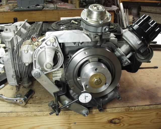
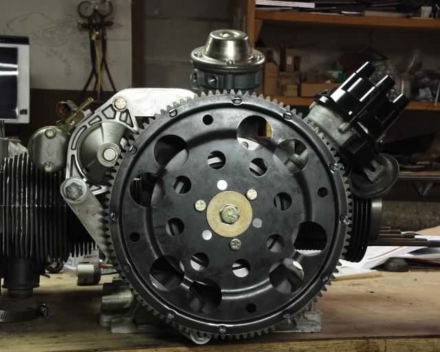
Rather than reface the harmonic balancer (which I figure should be perpendicular to the crankshaft bore by definition), I measured runout and then rotated the flexplate adapter to minimize it. At 1.5" from the centerline I had .004", which is only .014" at the ring gear. A rubber mallet would probably take care of the rest, but since I can't even SEE it, I don't think I'm going to worry about it.
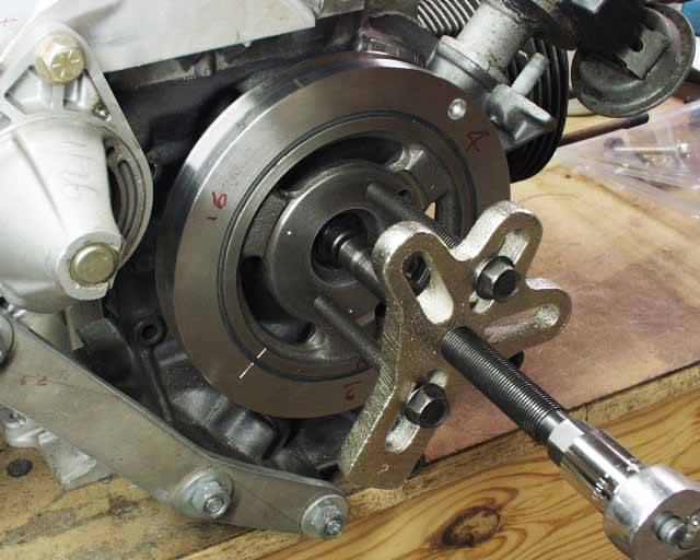
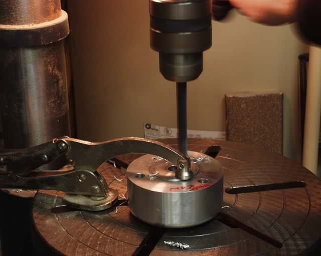
This Craftsman pulley puller is perfect for removing the harmonic balancer.
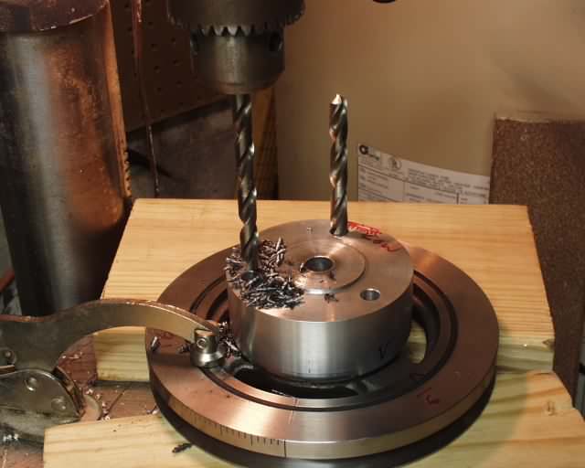
I had the aluminum flexplate adapter machined from a piece of 3.5" diameter 6061-T6. I then drilled holes to secure the flexplate to the three webs of the balancer. The adapter was then used as a drilling fixture to drill the balancer, and then the adapter holes were opened up to the proper 10mm diameter.
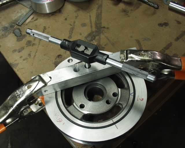
I'll be the first to admit that I'm not a machinist (but I did stay at a Holiday Inn Express last night!), so I used the drill press and a 1x1 aluminum bar to make a fixture that would align the tap so the threads would be coaxial with the hole.
If you have the nerve to throw away both the mechanical fuel pump AND the distributor in
favor of electric pump and electronic ignition, you can get away with a mere
2" clearance between the top of the case and cowling! The flex plate and
intake manifolds are the tallest things left. I may slide my engine up 3"
now, and add the carb below. This would keep me from having to add ground
clearance for the prop, and later on I could easily go to CIS fuel
injection, after the engine and airframe are proven. Of course this will
all be a moot point if the Sentra starter doesn't have the power to spin a
Corvair, but I'm betting that it will. This starter is physically very similar to the proven Ford Probe starter. We'll see. Until then, I wouldn't
start a stampede to Sentra starters. Next on the agenda is to dynamically balance all of the rotating masses at the speed shop, and then start assembling the engine.
updated April 15, 2001
Rereading the paragraph above, I must say that having played around with a KR2 cowling, I've decided that the intake manifold is not far behind the distributor and fuel pump in terms of engine height, so I've decided to leave the Weber carb on top and just build in a scoop/hump for it to live in.
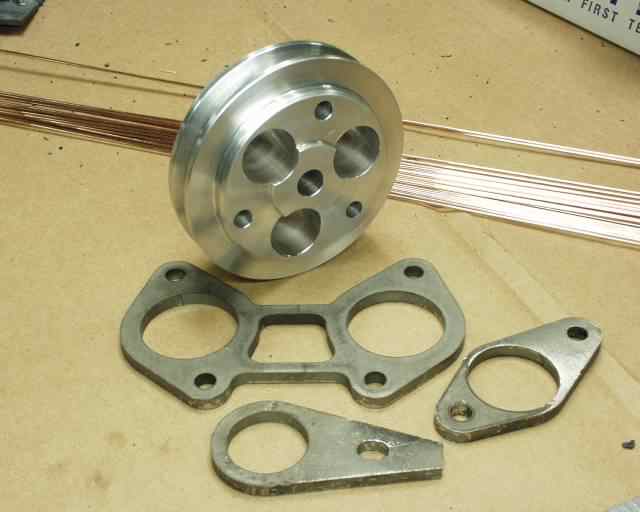
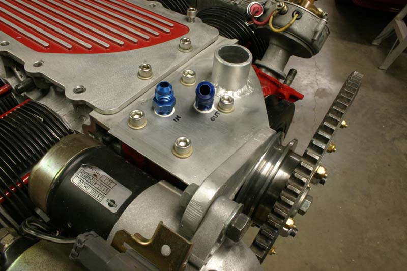
Given the fact that the stock pulley would spin my John Deere alternator about 3 times faster than it was designed for, I designed a new pulley groove into my flexplate spacer and had a local machine shop make it for me. Total weight of the pulley is 1 pound, 4 ounces. A drawing for this hub is provided at http://www.n56ml.com/corvair/flexplate_hub.pdf in pdf format. Use at your own risk, but I do have well over 500 hours on this pulley with zero problems of any kind.
I also had a lasercutting shop cut out the steel flanges for my intake and exhaust systems, some of which are also shown in this picture. The welding rod in the background is mild steel rod that I'm using to weld up my 4130 engine mount.
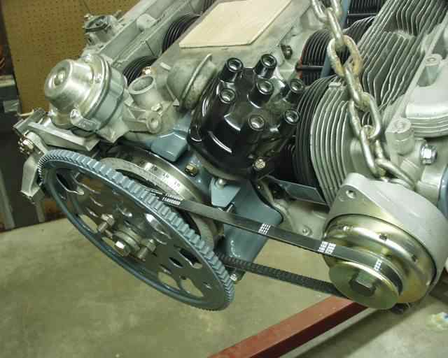
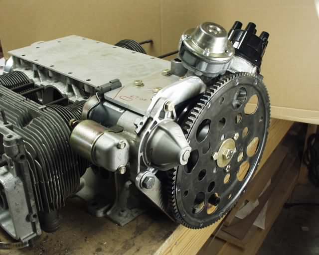
Here's the engine, hanging from the hoist during mount fabrication. Alternator and flexplate installation are final, except for the flexplate bolts and the upper alternator bracket. I also tested my little 16 Ah battery to see if it and the Sentra starter would turn the engine over, and they work great! The powder paint shop painted all the teeth on the ring gear, which I don't expect to last long.
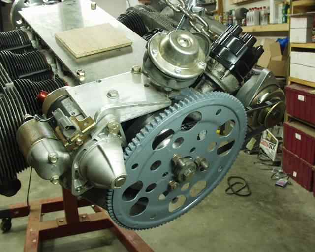
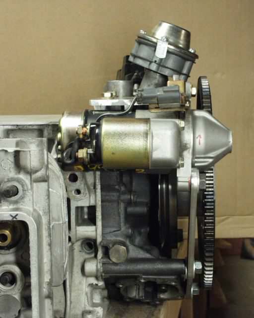
The view of the other side.
Project Update - as of May 5, 2002, the BETTER way to do the starter mount and oil connections!
My starter mount plate (former /generator filter adapter) was never welded together. Instead I opted to "braze" it with aluminum, something that I've never felt really good about. As mentioned above, this is a high pressure oil application, so I decided to make another one.
I bought a Lincoln Squarewave 175 TIG welder at Oshkosh last year, and expected that it would "change my life and the way I do things". Indeed it HAS!
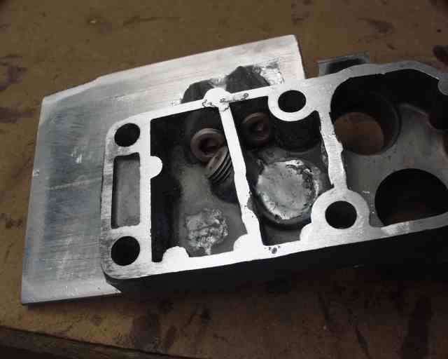
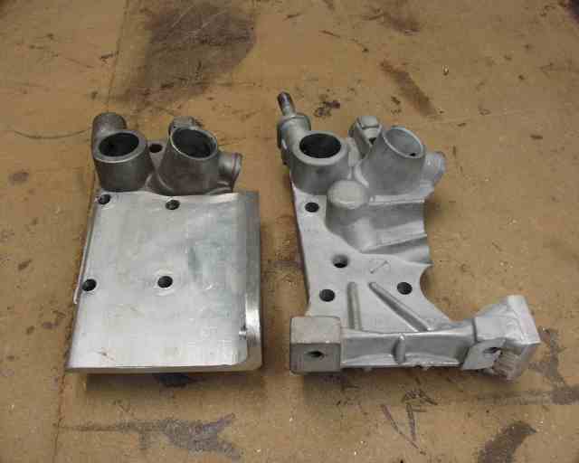
I bought another "generator adapter" for early Vairs from Lon at Corvair Underground, and installed it, leaving my starter in place. I lamented that if that bracket weren't angled, and shaped just a little differently, it would mount my starter just fine, while retaining the filter bypass and pressure sensor location, not to mention removing about 12 inches of potential oil leak territory where my brazing had been.
Because of my flywheel location, it was obvious that I had to cut the filter mount away, so I tried to cut it out in the middle so that I could use the filter mount remotely. I only wish that I'd thought about it a little more, and I'd have cut it at a 25 degree angle vertically, which would have made the cuts perpendicular to the oil passage, making it far easier to get the tap started straight.
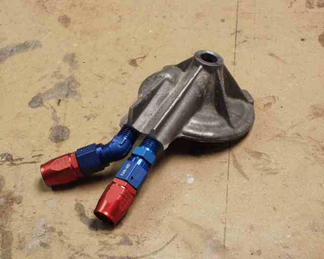
These holes are .75" on center, which leaves enough room for NPT/JIC adapters, but not enough to actually TURN the swivel nut on the hose, so I had to put an elbow on one of them to put some distance between the two swivel nuts. If I had intentionally angled my holes while tapping, I could have made them both fit. This filter adapter is very light, uses stock Corvair filters, and has the benefit of being able to mount (using the top bolt through an angle bracket of .090 aluminum) such that it can be rotated 360 degrees for any possible configuration. And best of all, it was FREE!
After looking at this "bad geometry" situation for a while, and considering my newfound ability to melt metal wherever I want it now, I occured to me that by simply welding a tab of aluminum into the right place, I could use the entire generator/filter adapter, bypass and all, and eliminate the effort and potential leakage of my previous design. I didn't have any 3/8" aluminum on hand, so I cut a chunk out of a piece of angle from the local recycler.
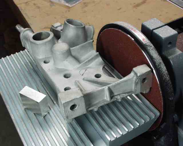
At first I thought I'd have to talk one of the guys at work into milling on my adapter a little to give me an accurate surface, but then it dawned on me that I'd just bought something that was about to become my "poor man's Bridgeport", a Delta disk/belt sander. I'm not sure how I lived so long without this thing. Troy Petteway commented that he built his entire airplane using one just like it, and I can see why!
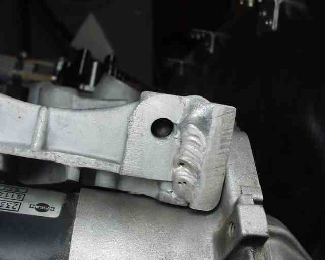
I'm not an expert on welding aluminum (yet), but I DO think this plate is stuck on here forever. The two blow holes are what happens when oil vapors given off by welding work their way up through the weld, creating a nice leakage path if high pressure oil is on one side (which it isn't, here). But the REAL welders at work still called this a "gorilla weld". It's ugly but strong as hell! I also melted a huge blob of aluminum into the back side of the little plate to give me a "boss" (however hideous it is) to give me more threads for the 10mm starter mounting bolt. It turns out that the little radius jived perfectly with the radius on the starter, a bonus.
I must say that this is one of the better ideas I've had with regards to the rear starter Corvair engine. I just wish I'd thought of it earlier. This keeps the stock Corvair oiling system (AND its bypasses) intact, just remotes the cooler and filter.
I think I've done about all I can do with this rear mount thing. See more on the oil system at http://www.n56ml.com/corvair/oil_system/.
I should also mention that now that William Wynne has lowered his front starter profile a few inches to allow a better streamlining of the cowling, there's no reason not to use his setup, unless you just want to do it differently. He is also selling a new KR2S cowling that fits his front starter setup, so there's another reason to use his. There is a slight disadvantage that the starter and dynamo are on the front, and therefore your CG will be somewhat further forward, but that should be easy enough to compensate for when you build your engine mount. This disadvantage may be offset by the fact that the dynamo is going to get some serious cooling up front, unlike mine, which is going to be getting pretty hot (although I'm sure it's no different than under the hood of a lawn tractor).
Update: March 2007
See the new 3100cc "Phoenix" engine for details on the most recent improvement to the rear starter setup (about 2/3 of the way down).
Return to Mark Langford's KR2S CorvAIRCRAFT engine project.