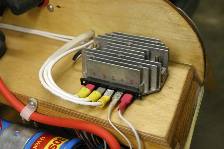
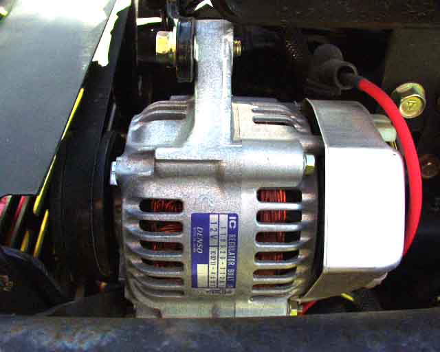
Here's how mine is wired. The terminals are labeled 1-5 in the photo (in red). Number 1 goes to the battery, 2 is the blue one from the dynamo, number 3 is from the blue and white dynamo wire (although I don't think it really matters which is which since it's AC), number 4 is to the positive side of the idiot light (the other end of the bulb goes directly to ground), and number 5 is power from my ignition switch (this is what enables the regulator to charge, not an output from the regulator). This way my ignition switch (which only provides power to the coils and fuel pumps) provides power, whether or not the rest of my electrical system is enabled. This also allows the idiot light to work only when the ignition switch is on, just like cars. My idiot light is an LED, and it glows when switched off, and slightly up to 1100 rpm when the dynamo starts charging. At 1400 rpm it's putting out 14 volts and and puts out 14.4V at 1500 rpm and higher. With a 10 amp load on it, it puts out about 14.2 volts. The case of the regulator is also grounded directly to the battery's negative pole. I used 10 ga wire for 1-3 and ground, 20 for number 4, and 16 for number 5, since it only powers coils and fuel pumps. Please note that I am spinning this using a smaller diameter pulley than the stock Corvair harmonic balancer provides, mainly because I'm spinning my engine faster than many folks will, and was concerned about over-revving the dynamo. Note that I've come back and shrink tubed all of the terminals (not just the two red ones shown) in the photo above, so there is no possibility of something falling across the terminals and shorting things out or starting a fire.
You may want to do it differently depending on how paranoid you are, or how much of Bob Knuckoll's failsafe advice you'd like to implement. This setup is the "dirt simple" version, without any of the safeguards that Bob expouses, but it's bound to be helpful in getting your installation up and running. Since my coils and fuel pumps are independent of the rest of my electrical system, I can just turn the whole thing off and keep flying, so I've skipped the crowbar stuff. Maybe I'll do some of that later on though. Subsequent tests have shown that pulling the 12V wire off of terminal 5 will stop the dynamo from charging. That also keeps the charging LED idiot light from working though, but it IS a means to stop a runaway dynamo. it would be easy enough to make a circuit to "turn off" the regulator this way in case of a runaway. In my case, main buss power comes from the battery, after running through a 25 amp circuit breaker.
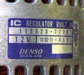
While at the John Deere dealership I spied this Denso 30 Amp alternator that looked pretty small and light, but this one requires a field current (like all "real" alternators). In fact, this alternator was on one end of an 1145 industrial mower's engine, while on the other end was a dynamo like mine. Chuck says the dynamo runs the electromagnetic PTO clutch, and was there as a measure to guarantee that even if the rest of the electrical system was toast, the mower would keep on cutting!
I should mention that John Deere also stocks a 35 amp version of this same dynamo, P/N AM877957, which uses same regulator, so I'm told. The only problem is that with a dynamo, it's always putting out the rated amount of current, since there is no field current control, so you are always "wasting" power if you are not consuming it all. Still, we're talking less than one horsepower. And besides, I now leave my landing lights on all the time and let those dissipate the power for me, increasing safety for "free".
update, July 2007
As of July 2007, I have almost 500 hours on this setup with no problems of any kind, and no EMI noise. Somebody on the CorvAircraft list said recently that "it's not a matter of IF a permanent magnet alternator will quit, but a matter of WHEN". I thought that was interesting, because the things are just so simple. But that sounds like a really blanket statement to me...there are reliable high quality examples of just about everything, as well as cheap junk that's not a fraction as reliable. Still, we are talking John Deere PM alternators here, although I believe Kubota and probably others use the same unit. So I dropped by the local small engine repair megaplex and asked about their reliability, and he said he couldn't remember anybody ever asking for one, and even if they did, they'd have to buy it from the dealer anyway.
OK, so then I dropped by the John Deere dealer and asked the guy at the counter how many of those he'd sold. The few he sells are almost always to the City of Huntsville, and that's because they run their industrial lawnmowers 8 hours a day all summer long, and even some in the winter. I asked what the mode of failure was and he said it was "always" the bearings locked up, and usually the thing was packed with dirt and grass to get it that way. It's a hard life on a bearing when packed with dirt and overheated, so that's not surprising. His opinion was that given the number of tractors that had been sold from his dealership, and the fact that when he did see a bad one, it has been in use forever and was practically physically abused, he thought you simply couldn't get anything more reliable. And it seems like he would know, because we already know that the dealer is the only place you can get one.
I asked about the regulators and he said "the only call I have for those is from the guys that are putting them on airplanes". It seems my web site has been responsible for some sales, since his address is there. It turns out the guy I was talking to was Chuck, the same guy that helped me find the wiring diagrams for them way back in November of 2000, so he wasn't hired just last week.
I'm not saying these things are bulletproof, but from the standpoint of a guy who repairs and sells John Deere equipment, it's pretty reliable stuff if you don't pack them full of dirt and overheat them, and even then they last for decades before giving up the ghost to a failed bearing. I do have 1000 hours on mine without any problem at all. By the way, mine is located about 3/4" behind my cylinder head and is bolted directly to the head! It recieves no blast cooling, just under-cowling air which is normally about 30 degrees hotter than ambient. Undercowling temperature does climb quite a bit after shutdown though. These things are designed to live under much tougher environmental conditions than my plane dishes out though, and I can tell you they work.
update, October 2005
I'm told that the John Deere alternator has been replaced by a different part number (MIA10338), which costs is $260.
Here's an alternative voltage regulator: It's only $83, and it works great, according to Al Hawkins from KRnet.
It's a Compufire 55121 "22 AMP 1981-1988 Black Finned, Big Twin Case", which is a replacement for a '91-'99 Harley Davidson Sportster, part number 74516-86. He now has 52 hours on his with a 17Ah Panasonic UPS battery.
update,September 2007
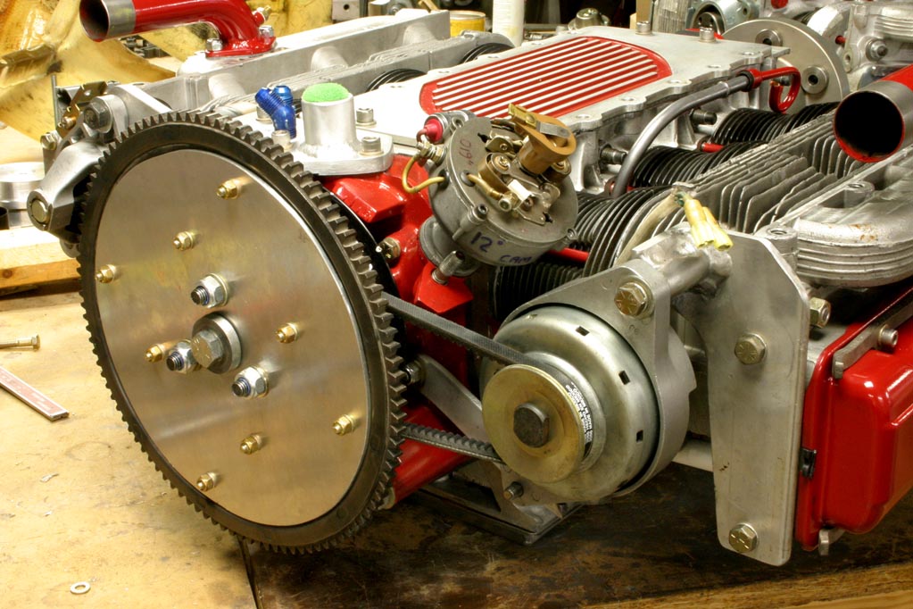
Here's the basic installation. It looks close to the cylinder baffles, and it is, but there's a plenum between the two. It now has 1000 hours on it without a problem other than the mount cracking, but the adjustment bolt held things tight enough to run fine until I noticed the loose belt.
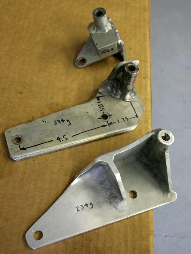
Here's the evolution of the main alternator bracket. The one at top is a flimsy thing that did OK for about 100 hours before it deformed enough for the belt to get a little loose. The next one made it another 400 hours before it cracked and separated completely at the weld (you can see the crack pretty clearly here). It set up a disconcerting vibration that I could feel in the cockpit as the belt orbited around with an inch of slack or so in it. This is a classic failure at a stress riser due to a drastic step in material thickness and the heat affected zone due to welding. Next is the latest incarnation, which will do much better. The welding is a little better, but still not great, and the load path isn't as optimal as it could be. It's hacked out of a piece of 3" channel, 3.0 x 2.0 x .233 x .156 6061-T6 using a bandsaw, with .190 ribs TIG'd in place. This one will probably last. It could still be improved upon in the load-path department, and it could use some big lightening holes as well. The adjustment bracket is just some 1" x .188 2024-T6 that's bent with a 1" offset and a 5/16" slot milled into it for the adjustment. Total height of the bracket at the main boss is 2.25" total.
Return to Mark Langford's KR2S project.