Mark Langford's KR2S - 2700cc engine
2700cc Engine
created August 1, 2005
The 2700cc engine was the quickest and most sensible way to get back in the air after the demise of my 3100cc engine, which broke it's crankshaft at 5000 ft. I did a "crankshaft post mortem web page" if you want more details on the failure analysis made by several aircraft crankshaft experts. Although I dare say that my 3100cc engine was assembled with more care and attention to detail than any other CorvAircraft powerplant, this engine will not be exactly like the last one, for obvious reasons. Major changes aret that it will be a 2700cc engine (stock displacement), I will index the prop correctly (vertical when the forward-most cylinder is at TDC), use a CNC'd Sensenich prop, and most importantly, nitride the crank to substantially improve fatigue resistance.
I've been sitting on this 95 hp engine for several years, bought from a local Corvair enthusiast for a hundred bucks. I personally removed it from a barn where generations of chickens had been roosting in it, but it still had all sparkplugs, carbs, and cooling tin (even the fan belt) in place. I'd venture to say that nobody's ever had this one apart, judging by the washers and fastener indications ("factory" mechanics have a nose for this stuff"). This thing is in far better shape internally than any Corvair I've ever seen...not that I've seen that many. After the case was washed at the local engine rebuilding emporium it looked brand new. There was hardly any evidence that the cam bores had ever seen a rotating cam.
The crank for this engine was originally from Jeff Ballard. His cranks have very generous fillet radii and he can have it shot peened as well. It's drilled for a William Wynne safety shaft, as well as grooved for the "Spirolok" ring (there's a photo coming below). The crank flange was doweled by Jeff, so it's not coming off anyway! The journals were ground by WW's crank grinder (as was my 3100cc crank), and then ion nitrided by Advanced Heat Treat Corp at 1625 Rose Street, Monroe, MI 48162 (ph 734-243-0063) to a depth of .008-.015. It was magnafluxed by Jeff Ballard for cracks before grinding and nitriding, and then magnafluxed again on my end by a NASA/nuclear qualified inspector that I work with, Charlie Rose. It should be noted that nitriding "erases" most of the beneficial compressive stresses that shot peening imparts (due to the 975F temperature of the process), so if you want both, you need to start with an almost stock dimension crank, deep nitride to about .025" (which takes about 40 hours of nitriding, and costs something like 400 bucks), then shot peen, and have the crank ground down .010", making sure nobody reduces the journal fillet radii in the process. Jeff only sells cranks exchange, so you have to provide him with a "stock dimension" crank that's not worn and hasn't been ground before. That's a tall order.
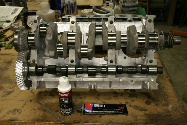
The cam is an OT-10 regrind. This worked out better than a new one, because the regrind is about .050" smaller in "lobe diameter", which meant I could use the stock pushrods, despite having .060" milled off each head's step. The remaining .035" difference in pushrod length is close enough for me. The cam has Clark's "failsafe" gear pressed on it, but I'm told that Jeff Ballard has a similar solution for about a hundred bucks less (I didn't know that until it was too late though).
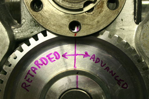
After assembly, I had a crisis one night when I started wondering if it was correct. Looking at the timing marks, and considering that the crank turns clockwise in this photo, the cam gear sure looks like it's retarded.
I thought I was going to have to split the case again, until I degreed the cam and proved that it was advanced, rather than retarded. I took the photo above to keep you from having the same crisis. You can also see the dowels and spiral snapring that ensure that this flange is never coming off the crank.
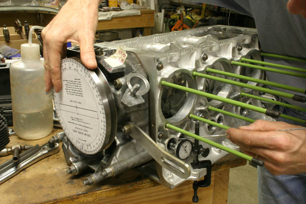
Degreeing the cam
revealed that the cam is advanced 5 degrees, similar to the 3100cc engine, which was 6 degrees. This appears to be somewhat normal, according to info that I've read about the OT-10. Lining up the timing marks is a little scary though, because they don't actually line up! They come close, and you have to figure out which way is closest, and which way is most desirable. Advanced is the way to go (cam mark to the right of the crank mark), which is closest to perfect alignment anyway.
The "steps" in the heads were removed down to the quench area (the flat part parallel to the piston top) for optimum detonation resistance. Ray Sedman did the machine boring work. He says optimal quench distance is between .022" and .042" of space between the piston top and the quench deck. He has set up engines this way that run 9.7:1 and can burn 87 octane fuel without detonation (in automotive use). The only way I could do this without removing material from the piston tops or the combustion chambers was to leave off the base gasket (using silicone instead) and use a .032" head gasket.
My deck height (distance the piston sits down in the cylinder) is -.0015 (it protrudes), so I'll have a quench distance of .0305" (.032 head gasket -.0015 deck height). This, combined with my cylinder volume of 51cc, would have given me a final compression ratio of 9.1:1, but I used thinner gaskets and eventually got up to 9.33:1. If I had simply "thrown the motor together" with stock gaskets I'd have 8.3:1 cr, been more susceptible to detonation, and would've left a few horsepower on the table. I hope to be able to run the 87 octane "autofuel" available at some airports, although my preferred fuel will be 93 octane, with an occasional tank of 100LL as availability warrants.
I installed new "Otto" racing guides and reamed to .3435", which leaves me with about .002" of guide-to-valve clearance. The manual calls for a .001" to .003", and since we're going to be running this engine hard, I want to be at the top end of the clearance range to allow plenty of clearance for the high rate of thermal expansion. I learned that a sharp reamer makes all the difference, so keep the reamer lubricated with kerosene or cutting oil. All seats were cut with Neway cutters (see the bottom of my headwork page).
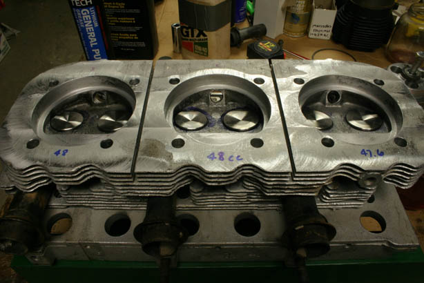
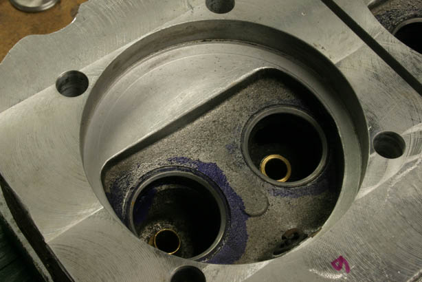
Like my 3100cc engine, this engine uses swirl polished stainless steel intake and exhaust valves. These are available from Corvair Underground, as well as from William Wynne. This photo is to remind me what the initial chamber volumes were. This head turned out to have 48cc chambers (which I've since equalized so that they are all 48cc), so I'll have to use .042" gaskets on this side, and .032 on the other. That'll give me 9.33:1 compression on one side, and 9.34:1 on the other side. That's close enough for KR work!
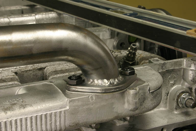
This time around, I'm bolting my intake tubes on, rather than welding them. This allows me the versatility to do things like change to a turbo or different intake setup, as well as allowing me to have a spare head that will fit either side of the engine. And the biggie for me is being able to clean debris out of the intake log after valve grinding or similar events, as well as being able to clean up the entrance port. When welding the intake tubes directly to the head, you have no idea what kind of penetration you're getting with that cast material (which is not that easy to weld anyway, since it's some ancient aluminum alloy that's been soaked in gasoline for 40 years), and you don't know if you've put a big blob of stuff in there that will impede flow in one direction or the other. Welding up a flanged tube and bolting it in place solves these problems, but introduces a new one of proper sealing under all conditions. William Wynne says he's had lots of problems sealing bolted flanged connections, which is why he now welds them all. I'm going to have some special three bolt flanges made (either laser or waterjet cut) to help solve that problem, but that will come later. Later: With 120 hours on the engine, I'll confess to having one intake leak on one side, but once retorqued, that was the end of it!.
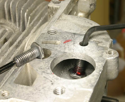
I made the studs from allen studs with low height nuts
welded to one end and ground sort of rounded, just short enough to stand up
inside the manifold. Then I used red Loctite on the allen wrench to allow
me to pull it up and start in in the hole. The second one shows the final
installation. 20/20 hindsight says I might just take a grade 5 hex head bolt and
drill a hole in the threaded end to replace the allen head hole, epoxy an
allen key into the end of it as shown in the first shot, and then do the
same thing with it. The thought of that low-height nut bouncing around in
the cylinder scares me a little. Although it IS welded to the stud to keep
the stud from pulling out, it could break loose, and the heat treat on the
stud is now compromised by the welding. I'd also like to make some thinner
flanges so I have enough room for a locknut. Steel flanges are about a buck a piece from Bugpack (for Volkswagens) and the tubes are U bends from
Magnum Force Racing
for $8, cut in half and welded. Grand total for the setup is ten bucks. I cut the carb flanges off with a reciprocating saw and then flattened pretty well with a belt sander, but since Ray was resurfacing the head gasket surfaces on his mill, I asked him to flatten them while he was at it. That's the beauty of the
bolted flange...I can change it next week if I feel like it. I always have
access!
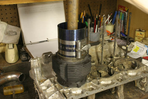
When it came time to install the pistons in the cylinders, I started having problems. I'm used to VW pistons, which don't have the rods attached yet (since they're a slip fit, rather than pressed onto the wrist pins). I needed a fixture to hold the cylinder while the piston and rod assembly was pushed in. An old Corvair case works perfectly!
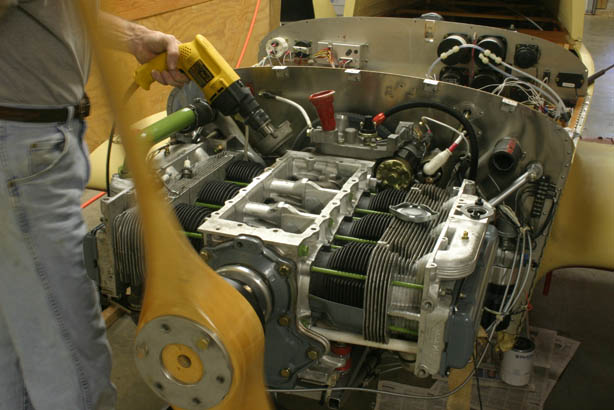
Once the engine was installed back in the airframe, I primed the oil system with a drill, using an old distributor with the gear and some of its guts missing. I didn't do this the first time around, and it took forever for the lifters to pump up. The thing ought to fire right up now and make no lifter noise. And everything's thoroughly lubricated already.
As I get closer to the KR Gathering (Sept 9th), my to-do list is as follows:
build a new cowling for shorter prop hub, which will also require new cooling plenums (I'm not gonna have time for this one though!)
add an extra fuel pump to regain the redundancy that I ditched when I made the system a bypass system to cure vapor lock
finish adding Tempurfoam to seats and have upholstered
install GPS on panel (using RAM mount pedestal)
rewire flaps with a momentary switch, and reroute wires better (through conduit)
reconfiguring the static system back to the original (I think it'll be fine with wheel pants)
creating a new aileron bellcrank cover that I lost somewhere over Madison county during testing
...
I have repossesed my cowling molds and will make a new carbon fiber cowling, but that'll have to be after the Gathering. I have a backup plan of using my old one and my old prop hub to get me there and back (but it sure won't be pretty!). I have a set of 10mm prop hub bolts that I'm having machined down to 7/32-24 threads to mate with the stock crank flange holes, so I can still revert to a Wynne prop hub afterwards. If that doesn't come through, I'll just rethread the flange to 3/8-24 and use some socket head cap screws that I already have in hand.
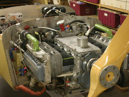
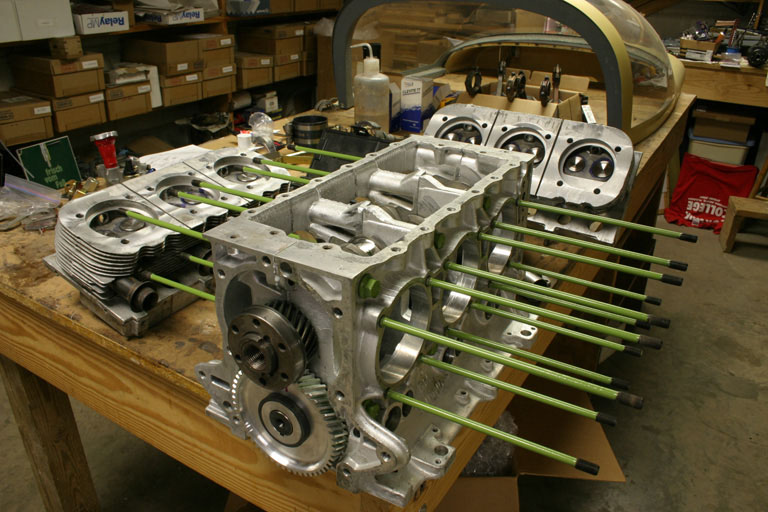
Green paint has no real significance, other than it's a can of rebar epoxy that Oscar Zuniga sent me, and it's ASTM certified to keep things from rusting. The day I started painting stuff I thought it would be kindof cool to color code this 2700cc engine as green, and make the 3100cc that I'll build over the winter red. That way I can tell the difference in them, in case I forget which engine I'm flying behind! Once the engine is up and running, I will do some vibration testing using John Kearney's x-y-z vibration setup to find resonant frequences that should be avoided in the future, and to compare my rear starter's vibrational characteristics to other CorvAircraft engines. Mike Sharkey will also provide something similar that I'll use to check the torsional bending at various rpms with the rear starter setup. This information should be invaluable to me, as well as other CorvAircraft engine builders.
After putting 270 hours on this engine, I did a "condition inpection". Check it out, and then see the new 3100cc Phoenix engine which I'm now running..
Return to Mark Langford's KR2S