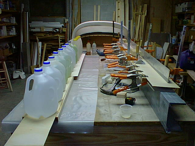
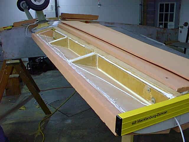
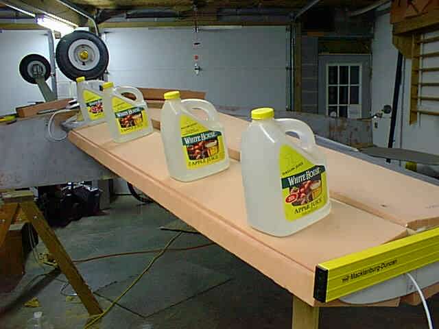
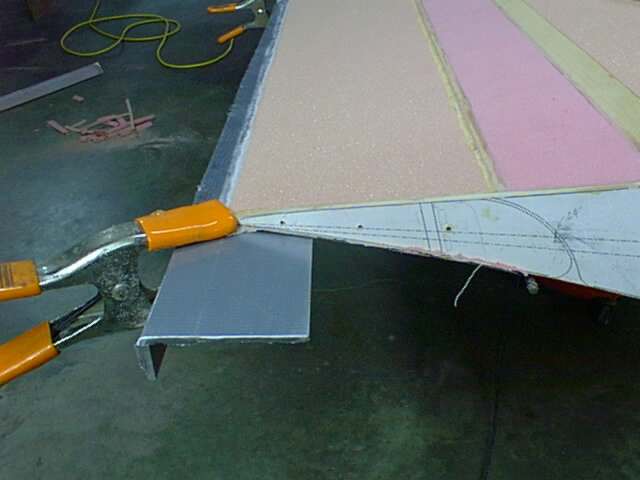
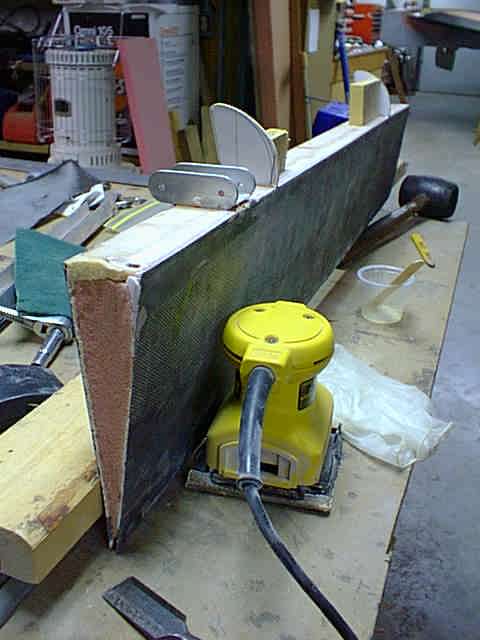
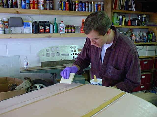
This is what you call using all of your resources. All my clamps were tied up on the pilot's side main spar on the right, so I used the old standby weights on the passenger side main spar face.
originally created Oct 11, 1998
revised January 20, 2000
This is what you call using all of your resources. All my clamps were tied up on the pilot's side main spar on the right, so I used the old standby weights on the passenger side main spar face.
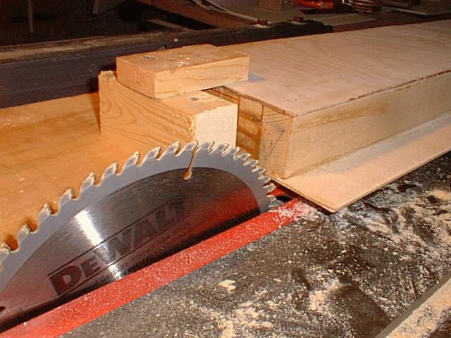
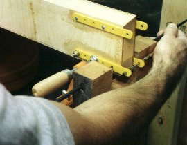
This rather primative looking setup was used to cut the taper on the spars. Both wing taper and airfoil taper were cut at the same time using this simple jig. It's nothing more than a straight 1x8 which had been run through the saw to rip the outer edge of the board as a guide for where your spar will be cut. After ripping, I fastened the spar in place, knowing that the edge of the board wass exactly where my spar would be cut. I also measured the taper that was needed on the top and bottom of the spar caps due to the airfoil shape. These angles were put into the edge of the blade and gradually changed (to account for the change in chord location of the spar) as the spar is pushed through the saw (a helper would be handy here).
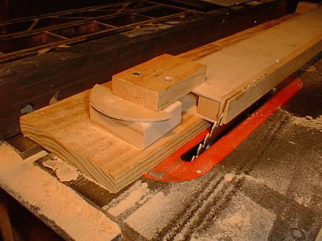
This jig doesn't have to be anything fancy, just enough to keep the spar from slipping as it's cut. This method is far more accurate than belt sanding the spar caps, which is a great way to cut unintentional grooves or remove too much material from your spars. Of course, you have to be careful using a table saw to make them too, but if you take your time and be careful, you'll get spars that fit your airfoils perfectly, and require no further work than the table saw does to them.
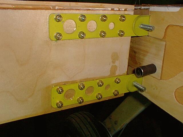
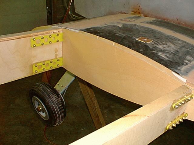
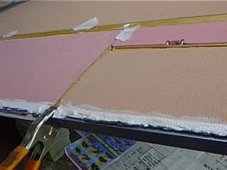
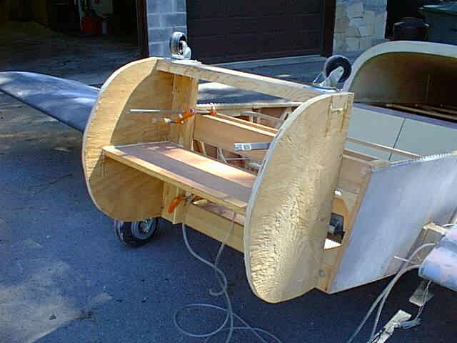
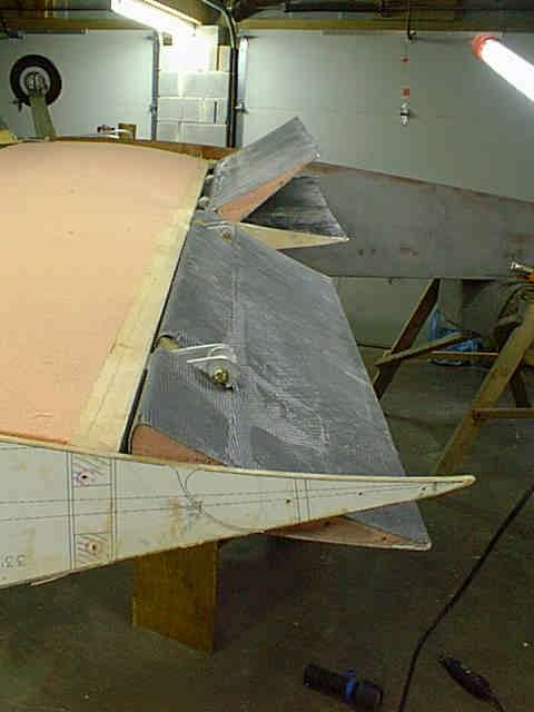
Now that the spars are tapered you can fasten them in place. Of course the fuselage must be leveled in both directions before proceeding (see the bottom of Stub Wings) for excruciating details on fuselage leveling and water level "contruction". I clamped my WAFs (wing attach fittings) in place temporarlily while trying to get the outboard spars in a direct line with the stub wing spars. Once I got the spar where I wanted it, I screwed the WAF to the spar using small #6 screws to make sure it would stay in place. You can temporarily clamp one set of WAFs in place, and if the spar tip is supported, you can jockey the other par of WAFs around to get them aligned with each other for drilling. I used this water level to ensure that the front side WAF was in line with the aft side WAF.
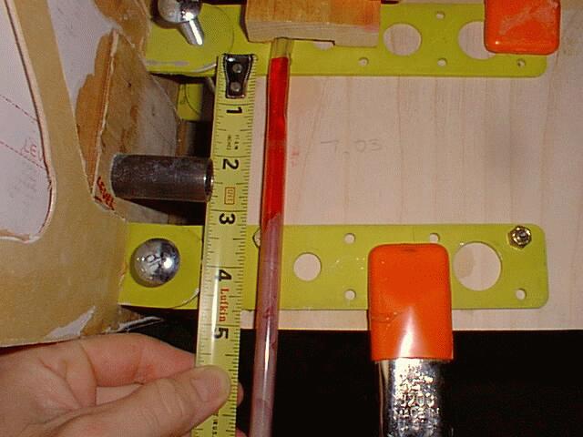
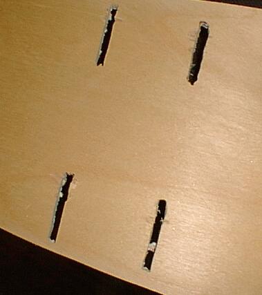
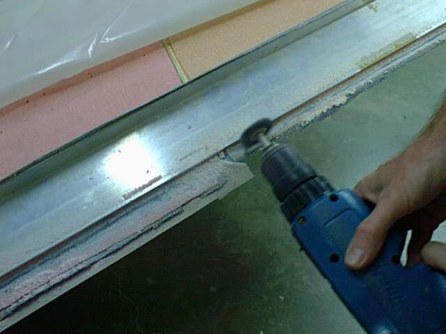
As on the stub wings, I used this spar drilling fixture to ensure that the hole I drilled came out in the middle of hole on the corresponding WAF on the other side of the spar. If you don't use one of these, you might as well throw your spars away right now and start over, because you will make a real mess of things.
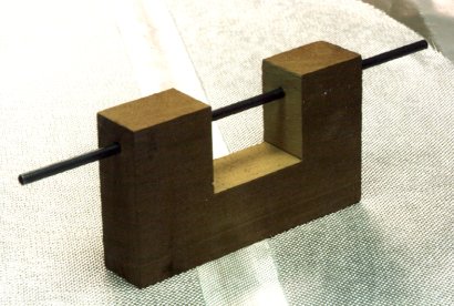
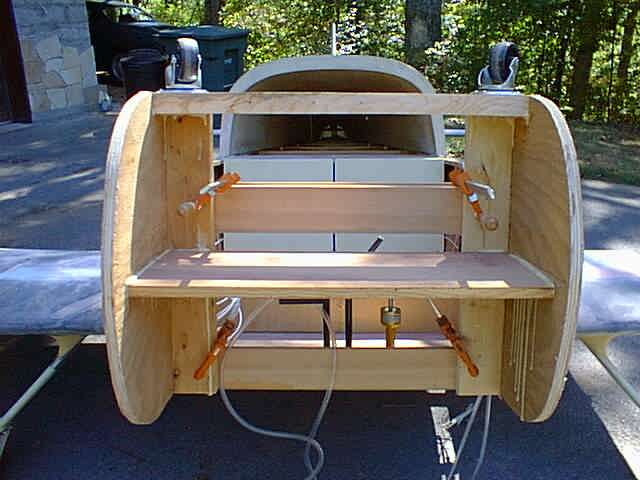
This tool allowed me to nail all of the holes exactly thru the center of each WAF on both sides. There is a steel model detailed in the plans, but I didn't have the metal working tools required to make it, so I made mine out of a block of Mahogony and 3/16" ID 4130 tubing. It works great. This picture was made prior to cutting out the 4130 tube in the center.
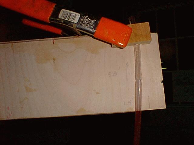
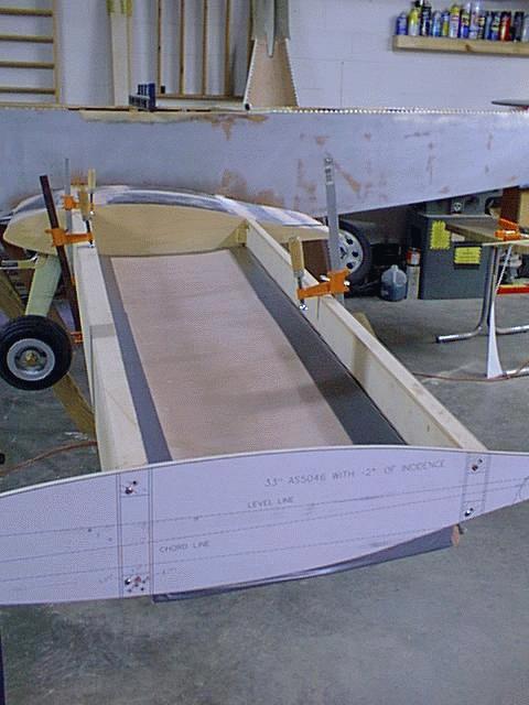
I also used the water level to ensure that the dihedral was the same on both sides of the plane. Dihedral is set by raising the bottom of the outboard tip of the main spar to an elevation 5" higher than the bottom of the root of the main spar. The water level is also used to set the washout of the wing by jacking up the aft spar (after the main is mounted) until the level line on the 33" template is level (more on that later).
It doesn't take long at all to have the outboard main spars mounted. I also epoxied my WAFs to the spars before bolting them so that friction wouldn't (it couldn't) be counted on for any strength in the joint.
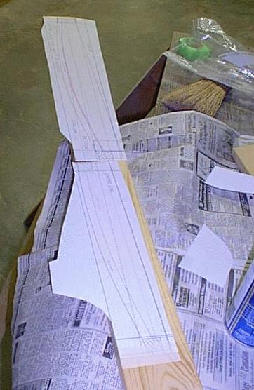
I cut a new AS5046" airfoil template to ensure an accurate airfoil at the root. This template would be removed later, so it was screwed to blocks which were temporarily epoxied to the spar. The 33" template was used to cut a 3/16" tip rib which would become part of the wing.
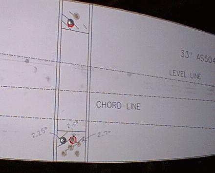
The outer rib template has a level line on it which corresponds to the proper washout when the rib is leveled. The fuselage is already leveled front to rear and side to side at this point. After installing the aft spar, the wing washout was within a fraction of a degree of where I wanted it, but I needed a little more work to nail it exactly. Some trial and error (to compensate for gravity) was in order. The wing tip template was rotated a little past where I wanted it to end up (using the main spar's torsional strength to pull the aft spar up) and screwed into the end of the bottom main spar cap. The holes that you see are several attempt, each within about .2 degrees of each other.
The outboard spars were then fastened in place and the aft WAFs drilled and epoxied.
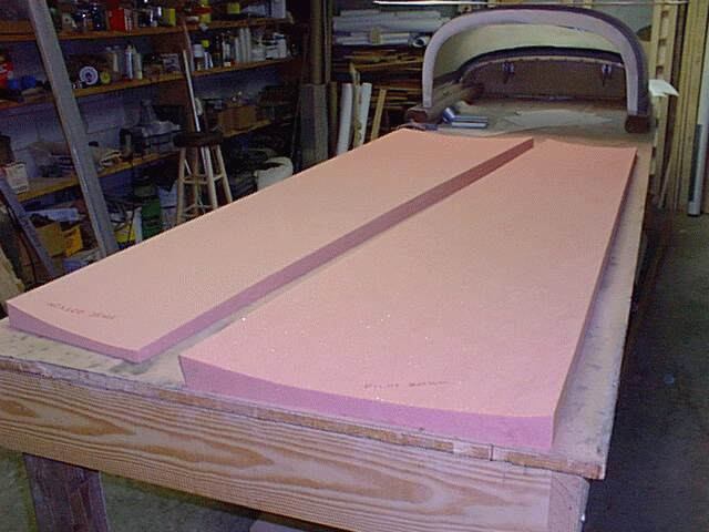
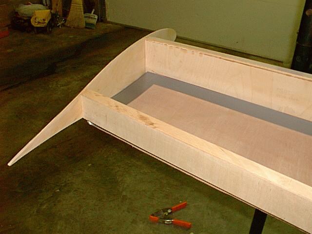
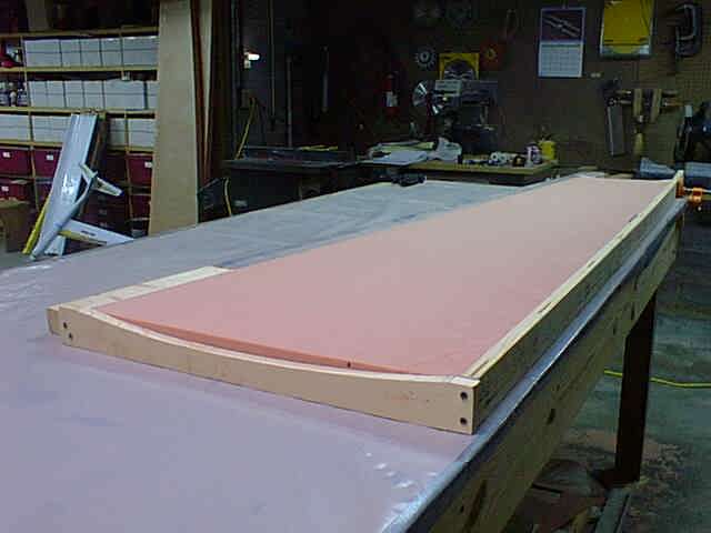
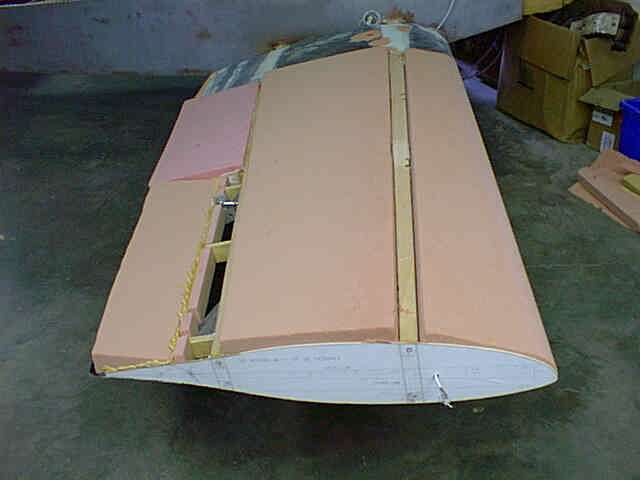
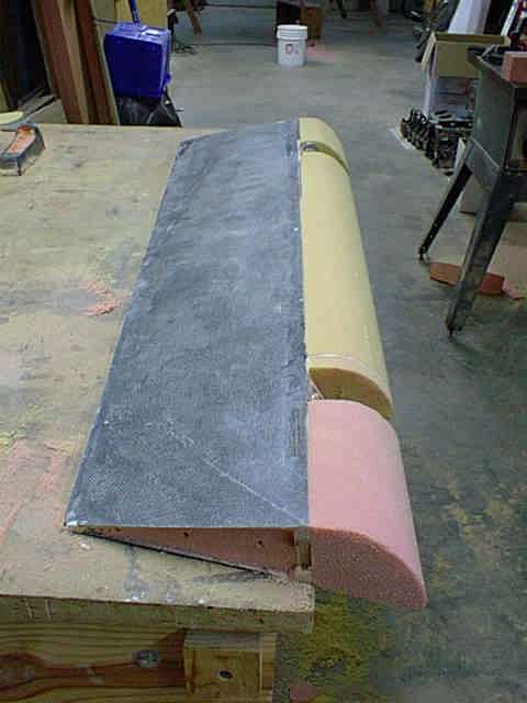
Now that both main and aft outboard spars were mounted, it was time to make my wing skins. Airfoil templates were generated which had a .4" offset to the inside. These plots were spray glued 3/4" pine to form the ends of the wing skin jig.
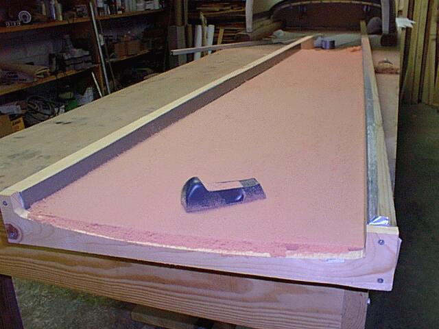
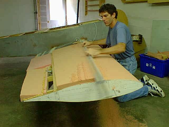
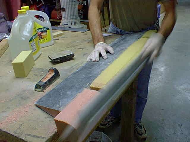
A Stanley Sureform(R) was used to rough shape the foam.
4" PVC pipe covered with self-adhesive floor sanding paper was used to finish up the airfoil shape. It only takes about 5 minutes.
Both wing skin shapes (interior, anyway) were complete in an hour or so.
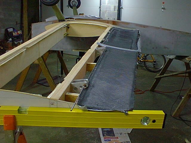
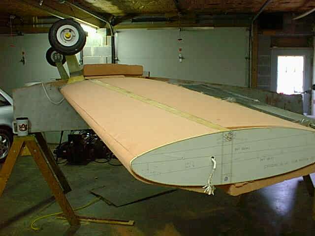
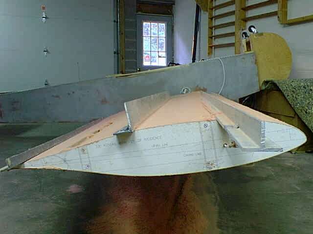
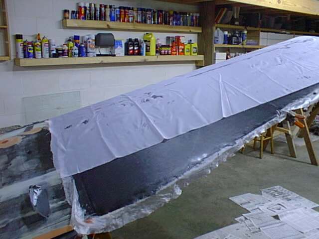
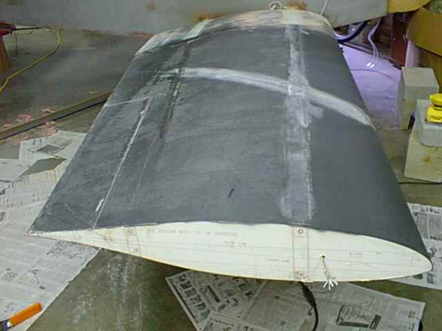
The inner surface of the wingskin was made in the same manner as the stub wing skins, with one layer of 5.85 oz KR glass laid up on the surface, running 45 degrees to the wing centerline. After curing, the edges were taped to allow them to be removed after creating a "ledge" for them to fasten to the spars. My plan was to remove the bottom skins and install the top skins in a like manner, except permanently. Since the top skin is under lower pressure, it needs to have a better connection than the lower skin. After the upper skin is installed, the lower skin is installed (and the wing "closed out" by simply applying some flox to the ledge and pressing the bottom skin into place.
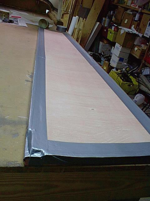
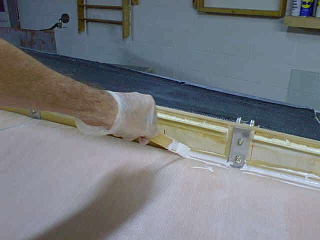
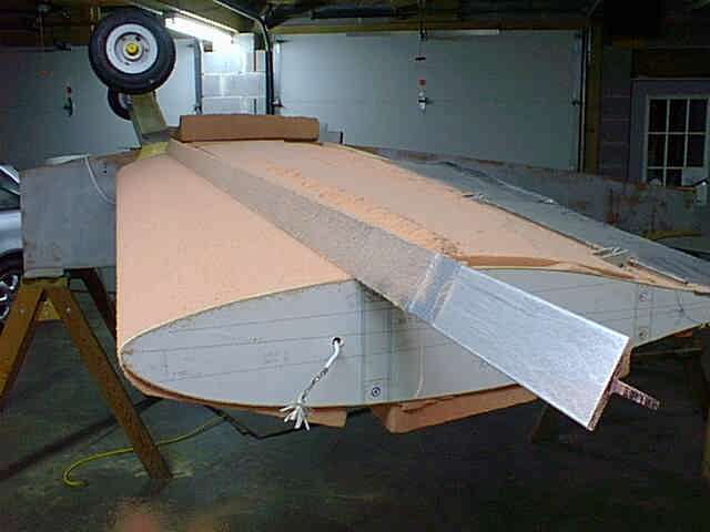
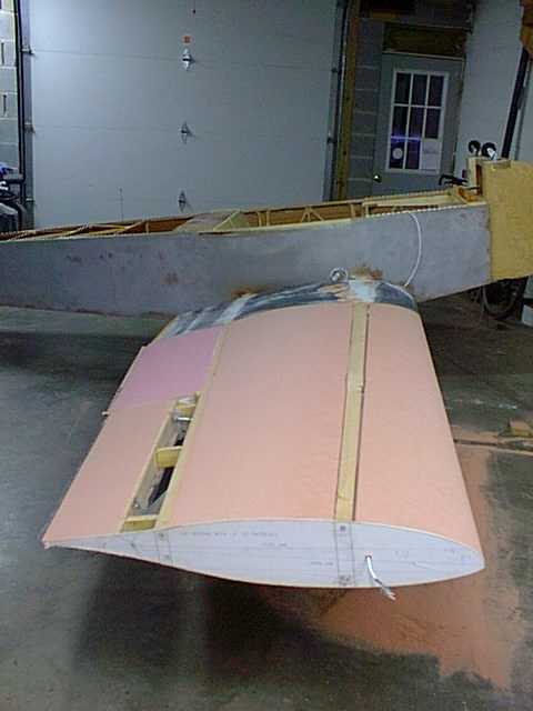
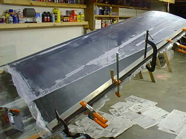
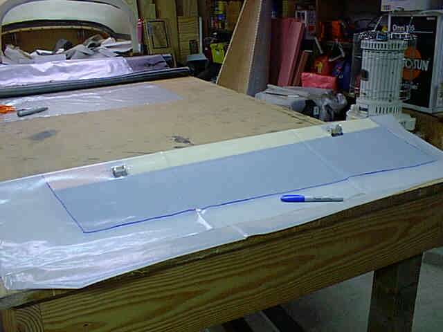
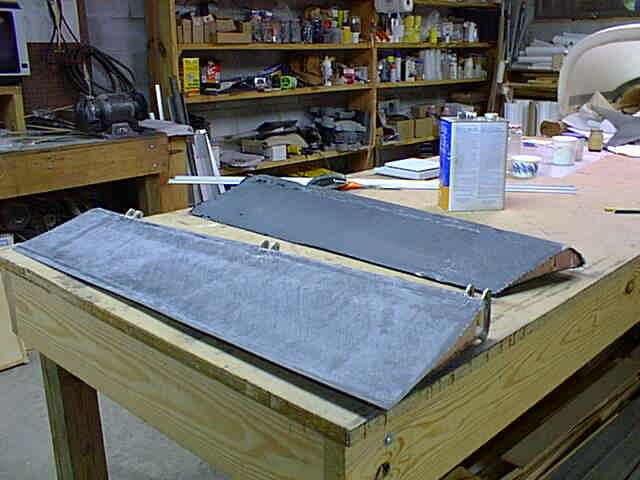
The lower skin is temporarily postioned, ready for two layers of 9oz tape to be installed at the joint between skin and spar.
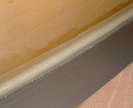
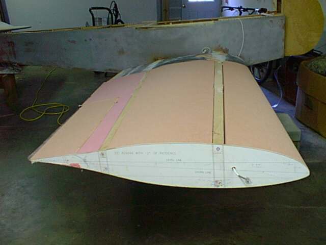
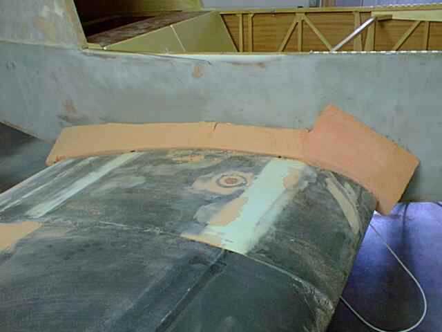
After smoothing a fillet of micro into the joint between the wing skin and spars, the two layers of tape were added all the way around the joint. The duct tape keeps the wing skin from sticking to the "ledges", so it can now easily be removed by sliding a putty knife between duct tape and ledge. With the bottom removed, the plane will be flipped over and the top skins applied in the same manner, but permanently (without the duct tape). Then, after adding aileron control mechanisms, ailerons, and flaps, the bottom will be floxed into place. Next will come the leading edge...and then the whole outside of the wing will be sanded to shape.
(One YEAR later...)
I'm now working on the outer wings. I'm building a flap and aileron system that is more conventional that those detailed in the plans. I should tell you that I've beefed up my aft spar to take the increased moment of these more effective control surfaces, and will cover my wings in two layers of carbon fiber to transmit even more of the loads from the aft spar to the main spar. My ailerons are roughly the same area as the stock KR2S plans call for, but are located much farther out on the spar, so roll control will be enhanced considerably due to the increased moment arm . Flaps are HUGE by comparison to the plans, at 42" long and 10" chord. This is roughly 5 times larger than stock, so I will have some serious landing lift. Since they are split, I will also have sufficient drag to slow me down and get the plane out of ground effect.
The top skin was made just like the bottom skin. The foam is surrounded by airfoil templates which have been offset the .375" skin thickness.
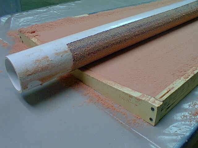
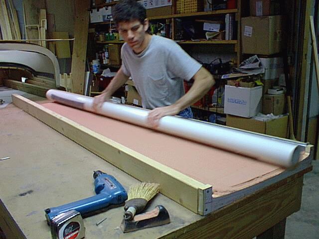
Again I used the big 4" PVC tube with 20 grit self-adhesive floor sander paper applied. This takes about 5 minutes.
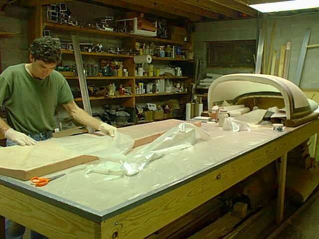
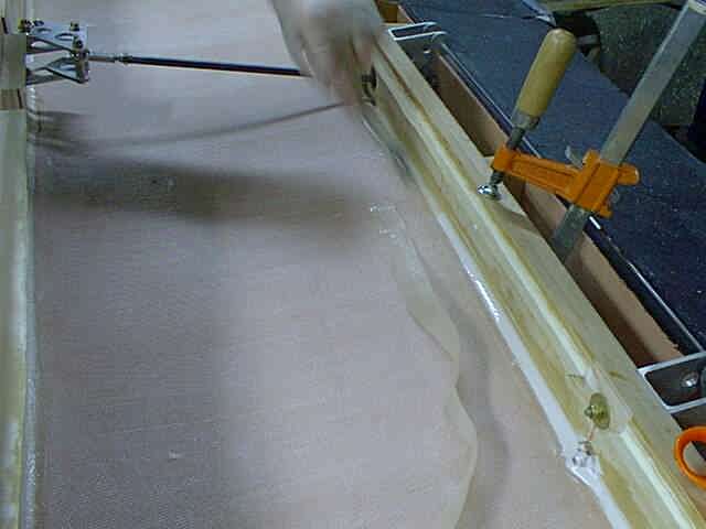
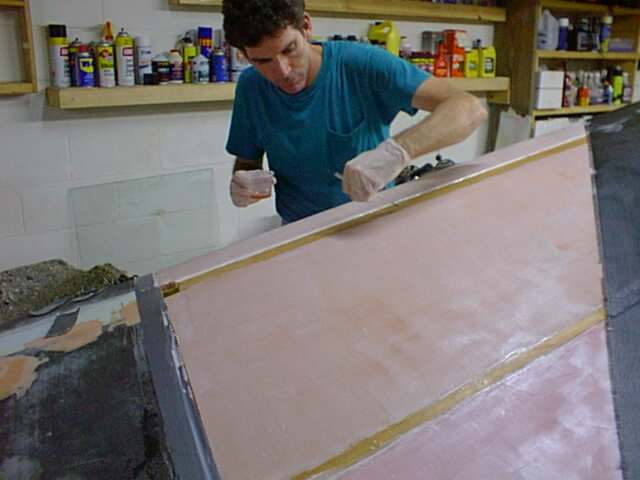
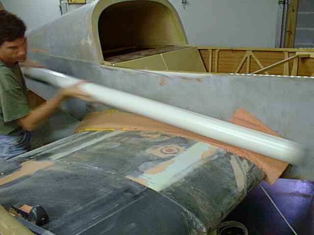
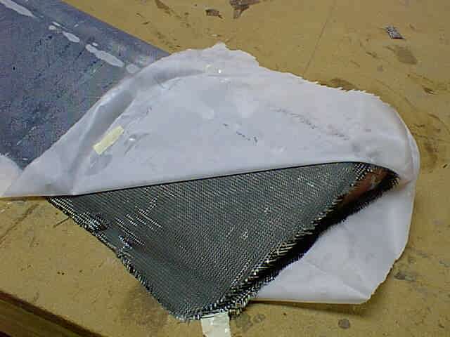
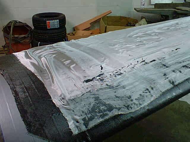
I used the time honored plastic sheet method to streamline the process. Here the sheet is being peeled back to expose the fully wetted out fiberglass, with weave still perfectly oriented.
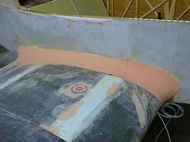
Immediately after glassing the top, I installed the skins into the wing, still wet. The skin was positioned at the proper depth between the spars and held in place with clamps. The joints were then filleted with micro.
One layer of 1" fiberglass tape was then applied to the micro joint to secure the skin to the spars. This is a lot stronger than it sounds. Besides, the inside skin is there mainly to stiffen the foam while sanding the airfoil contour, although it will substantially strengthen the wing skin as well.
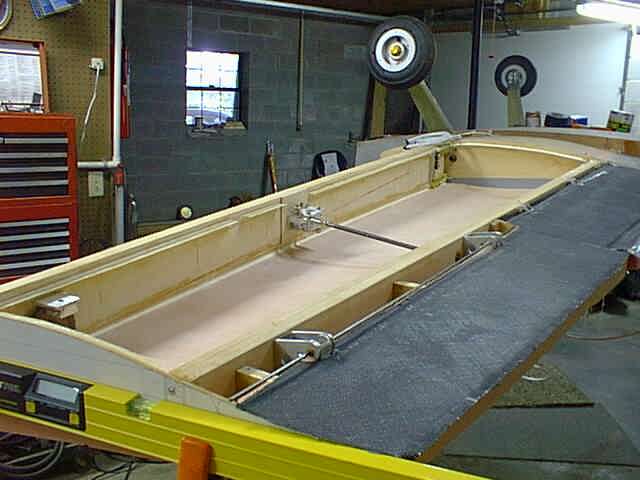
Here's the next day with aileron controls in place. Although I could have improved on the system some with a little foresight, I'm still amazed at it's simplicity. The wing is upside down in this photo, but here's how it works.
The stock RR stick connects to a cable that is almost on the cockpit floor, and exits the fuselage just above the longeron through a fairlead. This is not an optimal setup, as stick movement is contrained by the cable's fixed location at the fuselage wall. I will probably design a dual stick setup which uses the aileron cable axis as the pivot location for the stick, which will eliminate this "bias" on the elevator circuit.
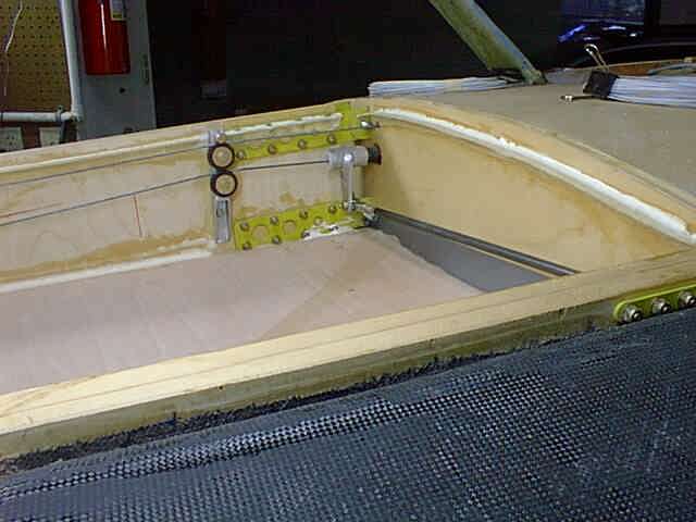
The cable runs thru a 3/4" aluminum conduit in the stub wing, in an area intentionally left open between main spar and wing tank. It exits the stub wing at the top of this picture. Here the hole is cut into a temporary airfoil template, which will be removed after the wings are completed and removed. The cable passes over a small pulley which slightly changes the angle of the cable to match the spar. The bottom pulley is for the aileron return cable.
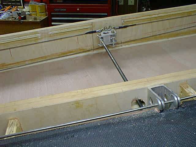
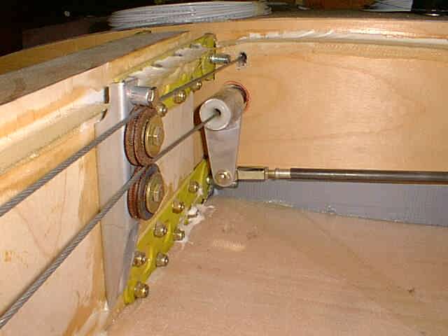
Next the cable connects to the aileron bellcrank, which is somewhat similar to the RR version, but not quite as perversely twisted. A 4130 steel pushrod actuates the aileron's bellcrank.
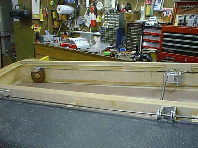
After the bellcrank the cable travels to a 3.5" return pulley, which changes direction and aims the cable back toward the other wing by way of the flap torque tube. The fairleads don't even touch the cable. The small guide pullies are perfectly in line with the center of the flap torque tube. The fairleads are there only to prevent chafing.
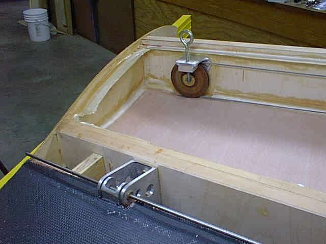
The return pulley bracket is constructed from 4" aluminum channel, which conveniently provides "cable guides" top and bottom to prevent the cable from falling off if it becomes slack. One of the legs has a block of aluminum welded to it to provide a threaded hole for the removable wing tie down rings.
Back at the stub wing, the return line direction is changed slightly and fed back to the other wing though the flap torque tube (note fairlead which fits pefectly inside the flap bellcrank). The flap bellcrank actuates the flap. The flap handle is mounted to the aft side of the main spar, rather than the front side of the aft spar.
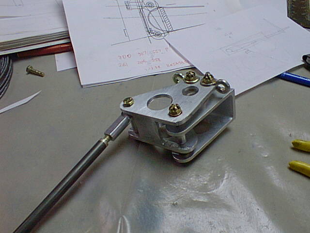
Here's a look at my aileron bellcran
k. It's made from a special 6061-T6 extrusion that's 1.5" x 3.0", .15" thick. About the only other stuff I could find was 6063-T3, which is NOT what you want to use here. This is mounted to the aft side of the main spar, rather than the front side of the aft spar
I really like this setup. I could've improved on it some more, given a little foresight, but it's pretty simple as is. Cable adjustment will be inside the fuselage with turnbuckles. The cables will easily slide thru the conduit and flap torque tube with thimbles attached.
Here the wing is almost closed out. The strobe light wire (a 5 conductor 22 gauge Tefzel coated shielded cable) is installed and secured with a few pieces of fiberglass tape. I'm using Kuntzleman strobes, a set of very small, lightweight streamlined double flash strobes that sell for $228.
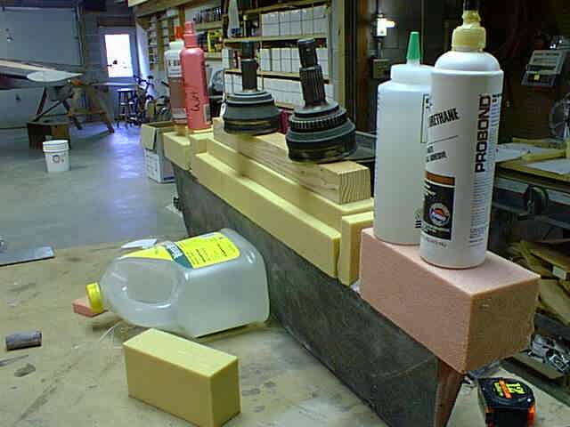
The leading edge "cap strips" were brushed with a layer of epoxy, and then microed. The leading edge was squished into place and precisely calibrated weights were carefully postioned. Care was taken to ensure that the joint between top and bottom of the leading edge would not have a bead of micro to sand. The seam was starved for micro at the very front of the leading edge, and no micro squeezed out of the joint. Micro in the joint will lead to REAL sanding difficulties, and the corruption of your leading edge profile.
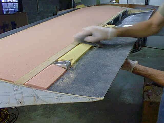
Sanding the rough contour of the bottom of the wing to shape was accomplished with this 8 foot long T-section aluminum, complete with 36 grit floor sanding paper stuck to the bottom.
In a few minutes, it was looking pretty good. Notice that joint at the leading edge, which has no micro or other filler in the crack. It'll be filled with micro at the same time that the carbon fiber skin is applied.
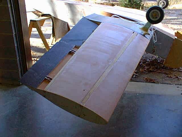
After the bottom was sanded to contour the plane was flipped over to reveal a topside that I hadn't seen in a year!
Another round of rough sanding with the T-section. Notice the two part epoxy foam that I used to secure the aileron to the spar. This all needs to be removed before sanding. I get the contour down to within about 1/8" with the 36 grit tool, and finish with a finer version.
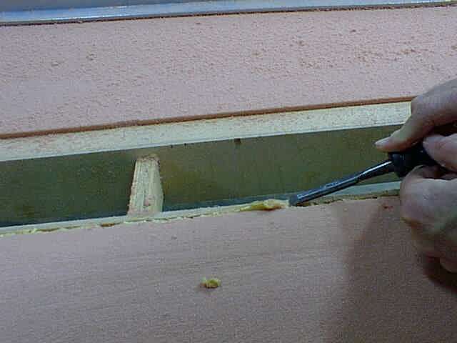
A wood chisel gets the big chunks...
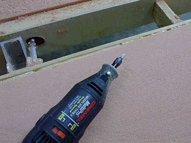
and the Dremel Tool(R) gets the rest. A round nose tool allows me to remove the foam to below grade level, while gives me more surface area for my flox/micro fillet to connect the spar to the skin when the time comes.
Here's the fine sanding tool, a 2 x 3 x 1/4" aluminum channel with 50 grit sandpaper glued to the short side. This thing is dead straight, and doesn't deflect in the middle with sanding pressure.
It took about an hour (and 5 gallons of urethane foam dust) to get to this point. Not bad, considering my ailerons and flaps are built, in place, and are ready to work. All I need is to wrap the the wing in carbon fiber, and cut them out afterwards. And there's little doubt that the flap and aileron will be perfectly aligned with the rest of the wing. The gaps between foam and spars is intentional. Again, this gives me more area for a fillet of flox and micro to help connect the skin to the wooden spars.
Here the wing foam is sanded and ready to "glass".
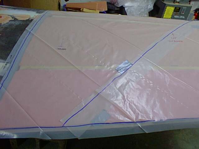
A little prior planning pays big dividends when glassing wings. I needed a pattern for the carbon fiber (CF) and since I use 4 mil plastic sheet to wet the stuff out anyway, I killed two birds with one stone. The plastic sheet (builder's variety) was cut into widths that were 2 inches wider than the CF, which left a 1" border around the CF for epoxy wetting purposes. By marking the plastic, I now had
a perfect template for my CF.
I clamped an aluminum angle below the trailing edge for support while I removed the micro from the CF so that the flox/micro trailing edge would stick to the CF better.
I used a wire brush and sandpaper to clean down to the carbon fiber.
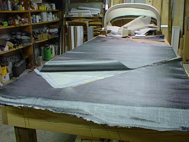
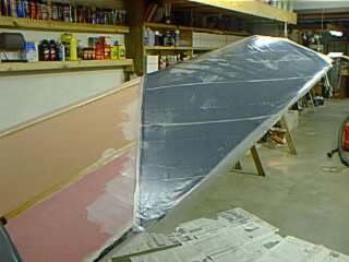
I took my plastic sheet and laid out and cut the CF to size. It only took two pieces to do the entire top surface and bottom of the leading edge.
I wanted to wrap the layer of CF around the leading edge to the bottom of the main spar. Jacking the plane up gave me plenty of room to operate underneath, as well as made the top surface a more comfortable height.
Here the trailing edge (at the ailron) is microed and floxed to make it very strong. After the CF is applied, an aluminum angle sandwich is applied to make the edge straight and uniform.
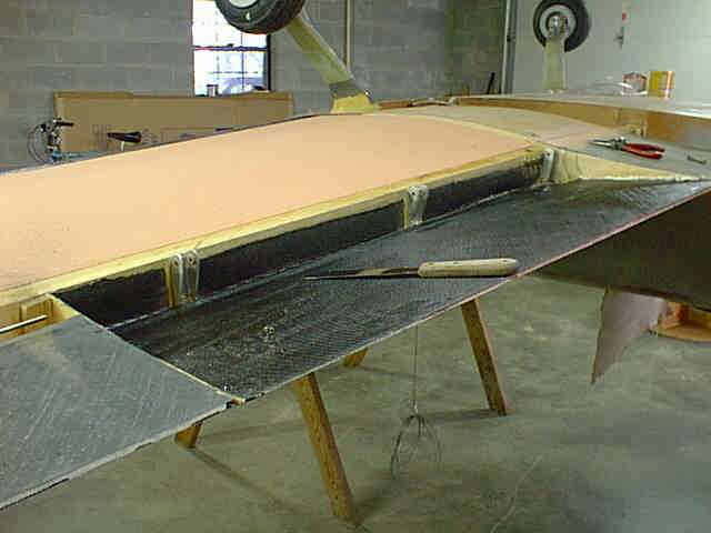
Here the first piece of CF is in place. This took longer than you might think, something like an hour. That's why I only microed the foam in the area where the first piece of CF was applied.
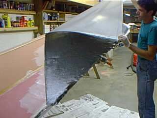
Wetting out the CF on the plastic ensures that the back side is completely wetted out, as well as keeps the weave straight and perpendicular. I keep hearing people say that CF is hard to wet out, but I have no idea where that comes from, especially if you wet the backside first like I do. Maybe they're doing it in the dark with cold epoxy or something. The CF is squeegeed into place through the plastic, and then the plastic is peeled away.
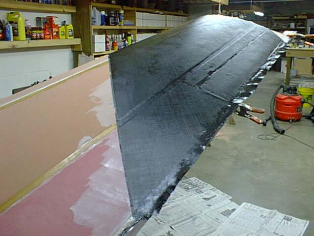
The CF is then squeegeed into close contact with the foam and micro again, just to make sure. You can see here that I intentionally built my spars about .030" short of the foam. This ensures that the spar will never be a high spot, which would required loads of heavy filler to bring up surrounding areas. By leaving the spars "low", I only have to smooth a thin layer of micro down into the low place, and sanding it smooth is a piece of cake.
Straight epoxy is brushed onto spars before the CF (or glass) is applied to ensure good contact with the spars.
Peel ply is applied to eliminate pinholes and to provide a good bonding surface for the bottom layer of CF, which will wrap around to the top of the main spar. The leading edge is so strong now, I'm seriously considering not overlapping the bottom layer though. The other layer of stuff that you see on the trailing edge is the thin 1.45 ounce "deck cloth". This stuff is also a good pinhole killer, and is applied from just aft of the main spar to the trailing edge.
Here the peelply is squeegeed into contact with the CF. I was finally done, but it took me a total of 5 hours to get here! I was busier than a one-legged paper hanger, too. I had planned every step, had everything laid out, and still had epoxy curing way before I'd have liked. I think my next wing will be in the dead of winter, and after it's all applied, I'll fire up a kerosene heater nearby. This time I did it exactly at the recommended 77 degrees (Aeropoxy), which my basement just happens to hover around during the summer.
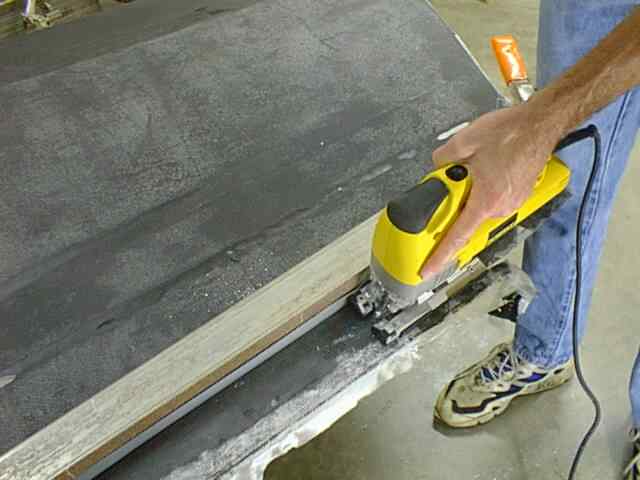
The next day I used the aluminum trailing edge angle to cut a nice trailing edge. What technology?
Here's what it looked like as I was scuffing up the CF before application of Aeropoxy Light filler.
I got tired of looking at those hideous gaps between fuselage and wings and threw some foam in there, held in place with ProBond urethane glue.
I used my favorite 4" PVC radius tool, with floor sander paper stuck to it.
15 minut
es it looked like this. Pretty hideous, so I'll rip it out and do again. But it was good practice...
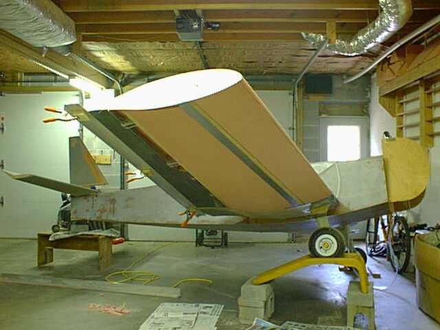
Well, it's starting to look a lot like an airplane. I put the aft deck back on for a little while so it would make me feel like I actually had an airplane under construction. It's fastened on with hinge pins, and only takes a minute to take off or put on.
I needed to flip the plane to finish "glassing" the bottom of the passenger wing, so I whipped up a flip-o-matic out of scrap plywood and 2x4's. Sloppy, yes, but it works great.
Nothing magic about this, but I'd have made it a little wider had my scraps been a little longer.
First thing I did after flipping it was pry out the flaps. These had been "built in place" for a perfect fit, and needed a little persuasion with a cake icing thingie to pop out and release from the duct tape. Being a split flap, the top of the wings stays fixed.
Next I removed the aileron (also sanded and built in place) and glued on some templates...
...and glued some foam to the spar for a nose using the quick setting polyurethan glue.
Next they were sanded to shape.
The bottom profile (the wing's upside down here)was sanded in place for a perfect contour. The plywood airfoil templates are part of the wing structure, and are glued solidly in place.
Hmmmmm. This ain't no schtinkin' KR! This obviously needs another layer of carbon fiber on the top side.
I did the usual plastic template thing, but with a slight variation that I may start using all the time. I taped the CF (carbon fiber) to the template so I could cut out the holes for the hinges.
I make sure everything is laid out ready to go, including peelply. No more Chinese firedrills for me! You know what they say...."proper prior planning prevents poor performance".
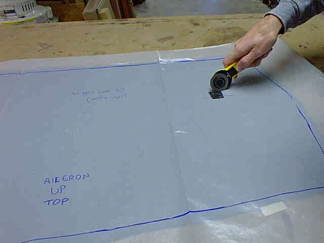
Here I used a "pizza cutter" razor knife to cut clearance holes for the hinges. Since they were marked on the plastic pattern, I knew exactly where they were.
After glassing, the peelply was removed. A little rough here, but 15 minutes later it was pretty nice.
Flap and aileron, ready to go. The ends of the flaps and ailerons will be closed out with a layer or two of carbon fiber, as if they needed it! I had originally planned to wrap both flaps and ailerons in two layers of carbon fiber, but I can't imagine breaking one of these flaps with only one layer. The aileron had to get two layers due to the nose and the way I constructed it in place, but only weighs 30 ounces total, hinges and all, and the flap weighs 28. The extra layer of CF on the flap would have cost me 8 extra ounces each for a total of a pound for the whole airplane. I think I can live without that extra baggage.
As Crocodile Dundee would say, "now THAT's a FLAP!" For those of you who never understood what a split flap is, now you know. You get the same amount of lift as a simple flap, but a whole lot more drag. That's just what the slippery KR needs to get it out of ground effect while skimming a foot off the runway. These little babies are going to shorten my landings considerably. They are 44 inches long and average 11" of chord. I'll be landing a lot on a 2700' sod strip at my father's farm in South Alabama, and there's a lake at one end of the runway that I'd like to avoid. The ailerons are 38 inches long and average 8" chord. They will be slightly more effective than stock KR2S ailerons due to the longer moment arm of their more outboard location, but will produce less drag, thanks to their shorter length (and shorter hinge gap).
You can see that the nose of this "Frise" aileron drops below the wing when up (as shown here), which produces drag to pull the lowered wing back in a turn. This helps turn the plane without the rudder. KR's do the same thing with their "differential" bellcrank action, by raising the inside aileron 20 degrees, while lowering the outside one only 10 degrees. I can tweak this too, since my aileron bellcrank is easily removable from the bottom of the wing. Maybe by next weekend I'll have the bottom of my wing covered, and then it's on to the other wing...
Saturday December 5, 1999 was one very productive day! Dr. Dean dropped in from Wisconsin, and Jim Hill (who lives in the South Pacific) showed up as well!
Since Dean was around to help, and weather was beautiful (65 degrees with dark blue skies) we worked outside some. This also slowed the curing process, extending our work time. When I laid up the first wing, I did it in two steps, first the top, and then the bottom. With such expert help as Dr. Dean around, we decided to do it all in one shot! Here we slurried the bottom. It was about this time that Jim Hill did two high speed flybys, right over the house! I heard him coming too. We heard what sounded like a VW go full throttle and I commented to Dean "I wouldn't be surprised if that was Jim Hill coming". Sure nuff...
Now this is some high priced help! And he sure does have some cool gloves! You couldn't ask for a better co-worker. Thanks a lot, Dean! I hope that cotton plant made it back in one piece.
This is a layer of 1.45 oz "deck cloth" that we covered the carbon fiber with. The whole wing has one continuous layer of carbon fiber, trailing edge to trailing edge at a 45 degree angle, and the leading edge has one extra layer added, top of front spar to bottom of front spar. The deck cloth leaves a silky smooth finish that completely eliminates pinholes. I usually put the deck cloth against the plastic, with the 5.85 ounce cloth on top, but forgot to do it this time. It would have avoided this entire step, but this way you get to see a picture of it. The flaps and ailerons are already built, with controls hooked up and hinges installed. All I have to do is cut them out and they're done!
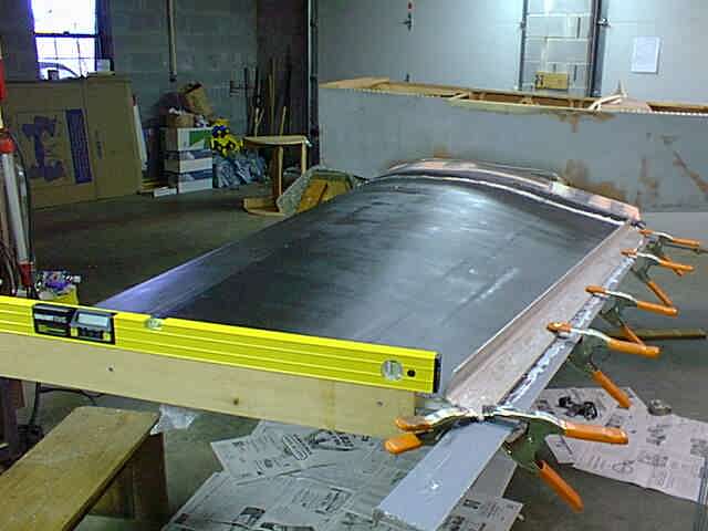
Here's the final product on Sunday morning. We had two little emergencies immediately after the layup. We thought we'd check the tip incidence just to make sure that nothing had changed. The first wing had 2.4 degrees of washout, root to tip, and I had set this one the same way. I had really been shooting for 2.3 on the first one, but during the layup process it changed by .1 degree. We checked the chord line at the tip and discovered it was off by 1.1 degrees! Panic set in, and we started dreaming up ways to tweak the wing before the CF cured, while guessing how much "spring back" we'd get when we removed the torque. Then it dawned on me. We were measuring fuselage level, not wing root level, and it was really only off .1 degrees! It was Miller Time! Then after thinking about it some more, it was apparent that the .1 degree would probably come out after all of that aluminum (used to make the trailing edge flox perfectly flat and uniform) and clamps were removed. I checked it this morning and it's dead on 1.4 degrees!
If you'd like to find out why I'm doing flaps and ailerons the way I'm doing them, check my "Opinions" at http://www.n56ml.com/kopinion.html.
I'm stashing the picture below here so I don't forget where it is...
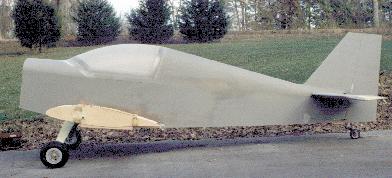
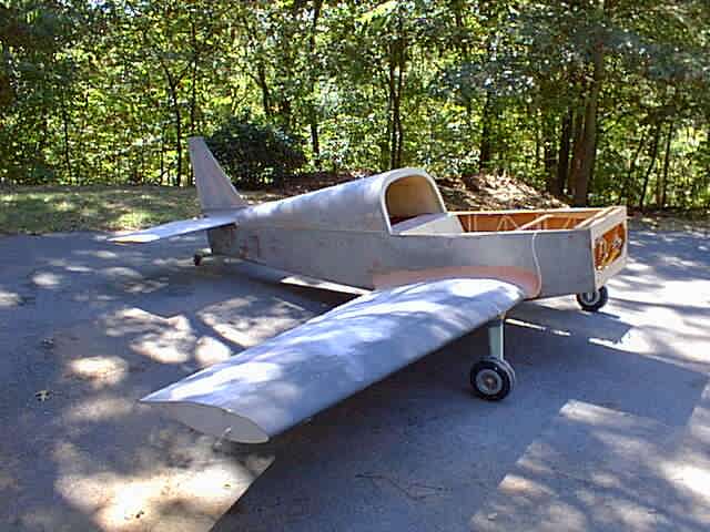
A pure side view that I will digitize and use to develop a nice cowling profile from. I left my firewall stock because I didn't want to be forced to build my own cowling, but I now wish that I had widened the firewall, as well as deepened it, to make the cowling lines blend into the fuselage a little nicer. Maybe on the next plane...
Return to the KR2S Construction.