Wing Construction
Wing Construction
revised July 10, 1998
Center Section Spars
"Scarfing" is the practice of splicing plywood so that short pieces of plywood can be used to span long distances. On the KR, it is required on both the fuselage skins and spar webs. The angle of the splice should be 10 to 12 degrees to maintain strength across the joint. Also, joints should coincide with structural members, such as spar webs or fuselage truss members. Spars require a joint because grain orientation should be vertical, while 4'x8' sheets of birch ply normally have grain running lengthwise.
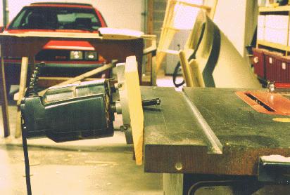
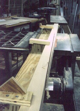
This scarfer is made by mating a regular plunge router (this one costs about $50) to a table saw. Obviously, you really only need a table saw to cut the chamfer, but it does make a nice heavy table for scarfing. You could just as easily use a large work table as the base.
First, set the table saw for a 5.5 degree cut (for a 1:12 joint, or 6.5 degree cut for a 10:1 joint), and run a 1 x 6 through on edge to chamfer a corner on the board. Then drill the board for three router mounting holes (two are countersunk) and connect the assembly to the table saw with two 1/4 inch bolts. Use a long (2-3 inch) straight cutting bit to do the cutting. Adjust the bit so it doesn't interfere with your table top, and go to town. Keep pressure on the plywood to ensure contact with the table while you're scarfing.
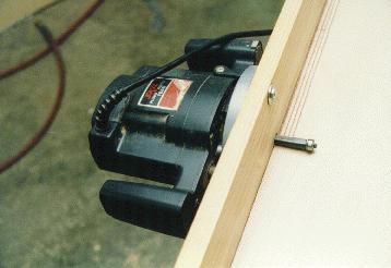
Make sure you feed your material from the same end as you would if you were sawing, or the router will take your plywood away from you and put a big dent in your garage door.
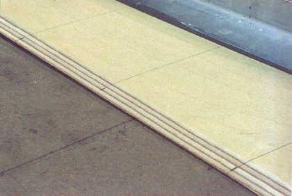
As you can see, these joints are just about perfect. Glue the joints together sandwiched between a flat surface (waxed glass, or duct taped glass) and spring clamps or weights.
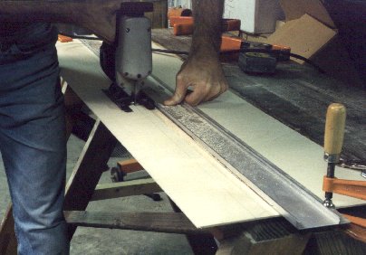
You'll need to cut the birch ply into strips. I used a jigsaw with a fine blade, held tightly against an aluminum straightedge to ensure a straight cut.
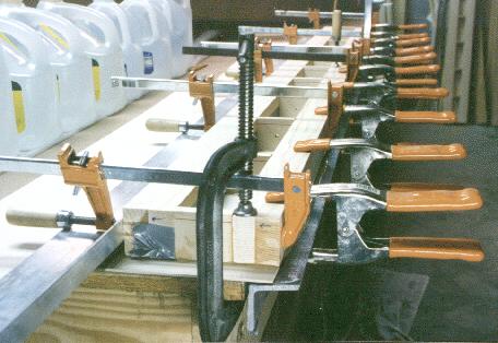
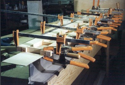
The next step for most of us is to laminate two pieces of spruce together to make each spar cap. This is the time to go to your local builder's store and buy WAY more clamps than you think you'll ever need to build this plane. You'll need them all later anyway, so just go ahead and do it now. I used the spring clamps that look like huge pliers for this job, since they continue to apply pressure to the joint even after most of the epoxy has squeezed out. Pipe clamps and the Jorgensen type screw clamps will loosen up after the excess epoxy squeezes out, allowing things to slide around. I always apply the epoxy to BOTH surfaces to be joined. This way I'm sure that all surfaces will have epoxy on them, and this allows the T-88 to soak into the wood on both surfaces. If you just put the epoxy on one surface and immediately clamp them together, most of it will squeeze out before having a chance to soak into the wood, and you'll have a poor glue joint. I'll be the first to admit that all of the glue squeezed out in the photo above is a wretched waste of glue, but I also have no doubt that there are no voids between the two members of my spar caps. By the way, I used T-88 epoxy partly because it's reputed to be the best product for joining wood, and partly because it cures completely down to 50 degrees. My basement stays around 60 during the winter months.
Also, an eight foot aluminum I beam or channel is very handy for a straightedge. I bought a 4"x6" aluminum C-section beam for $35 at my local scrap metal emporium. This was my platform for all spar work, and ensured that the spar was straight in all dimensions. Cover it with duct tape to prevent the epoxy from sticking to it.
Apply epoxy to both members to be glued. There's almost no such thing as too much epoxy here. You must have a perfect joint, and any excess will squeeze out between them. If you run out of spring clamps (like I did) make sure to come back and tighten any screw clamps on a regular basis until no more glue squeezes out of the joint. Also clamp the two boards side to side (on the ends and in the middle) to prevent them from sliding away from each other.
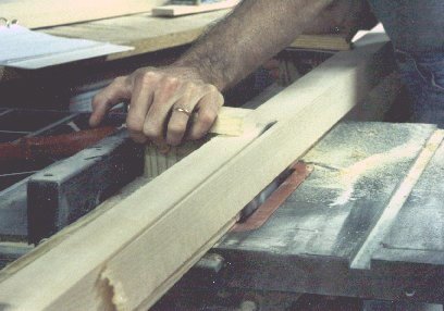
Next, run the laminated spar caps through a table saw to eliminate the squeeze-out and get the cap down to dimension. This is great time to check your saw blade with a carpenter's square to ensure that the blade is perpendicular to the table. I'd make them 1/32" oversize, so that you can sand away the sawblade marks. I also ran mine through a jointer to make them perfectly square and smooth. Now you're ready to cut the vertical members.
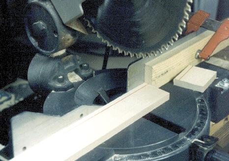
I used a stop block clamped to my miter saw's fence, so that all verticals will be exactly the same length. I also marked the board with a red stripe along one edge before cutting. This way, all of the verticals can be assembled in the same orientation, and any out-of-square problems with the fence/blade relationship can be cancelled out. Nonetheless, this is an excellent time to make sure that your blade really is 90 degrees from the table and the fence, BEFORE you start cutting.
The spar build-up is accomplished in several steps. This way, you can maintain more control over each joint. You'll have more clamps applied to each surface, and you'll be able to monitor clamping to ensure that there are no gaps between verticals, plywood, and caps. Any gaps are really bad news, and are cause to start over. I know. This was my second set. On my first set I tried to do it all at once. The day after glueing, I was shocked at the number of glue joints that contained air, rather than epoxy. I vowed to do better on the next one.
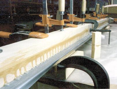
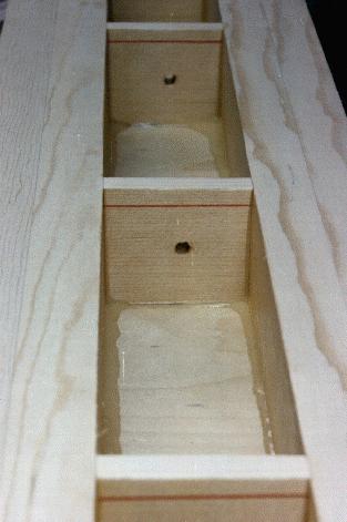
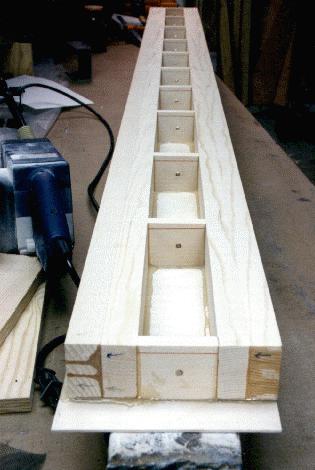
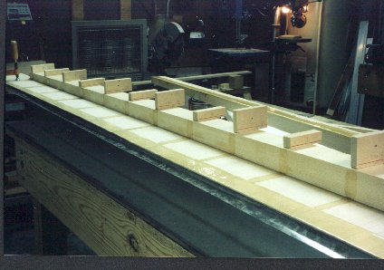
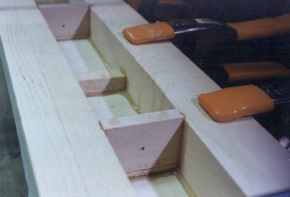
The first step of spar assembly was to glue all of the verticals to one of the spar caps. Notice that all verticals have been installed with the red stripe up, facing you, to ensure that all angular cutting errors are oriented the same. Don't forget to drill holes in the center of each one so that internal pressures can be relieved as the plane changes altitude rapidly. There have been reports of similar spars relieving pressures in other less desirable ways.
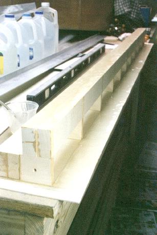
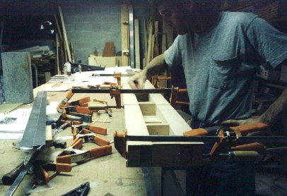
Next I covered the other spar cap's mating surface with duct tape (to act as a release agent) and used it as a straight edge to apply even pressure to the verticals. Notice the aluminum extrusion below the plywood, used to exert even pressure against the plywood onto the spar cap. This is critical. I tried stapling on my first attempt, and got a pretty wavy gap, and a lot of staples to remove.
Epoxy only one end of the verticals to the spar cap (on the right, in this picture). Also epoxy the spar cap (right) and the verticals to one of the 2.5mm birch plywood faces. My plywood was a little long in this picture, for no particular reason, but it caught lots of excess epoxy that would have ended up on the floor. Notice the use of an aluminum extrusion (clamped to the left) to ensure that all of this stuff was straight when being epoxied to the plywood. Let this cure for a day.
Here, epoxy is being applied to the other side of the verticals, as well as to the other spar cap. Next, the spar will be placed into the epoxy and clamped just like the previous stage.
After curing, you should end up with something like this, lots of squeeze-out everywhere you look. And T-88 is capable of filling up to 1/16" gaps. Yep, it's extra weight, but there's little doubt that full contact was achieved. You could either wipe it up or use it for varnish inside the spar. Now is a good time to coat all internal surfaces (except those which will be epoxied to the remaining plywood face) with polyurethane or epoxy. Polyurethane goes on thinner, and is therefore lighter. Use it anywhere that ultraviolet light will not be a factor. I sincerely hope that the sun will never shine inside this spar. A pipe cleaner does a dandy job getting to the inside of the breather holes.
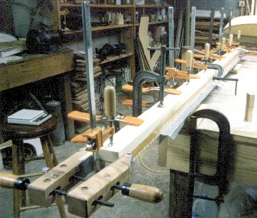
Since the first stage of assembly (using the aluminum extrusion) assures that the spar is straight in the plane of the plywood, I didn't have to worry about that direction anymore. A four inch I beam was used to ensure straightness in the other, less critical direction. A six incher would be better, but this is all I had laying around.
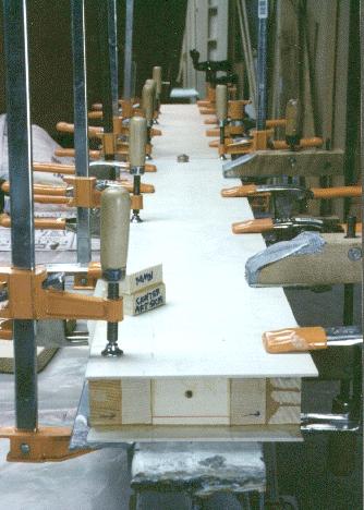
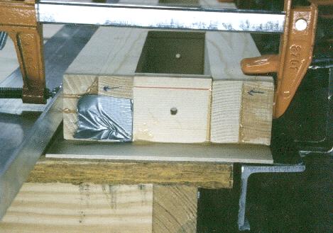
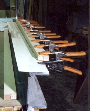
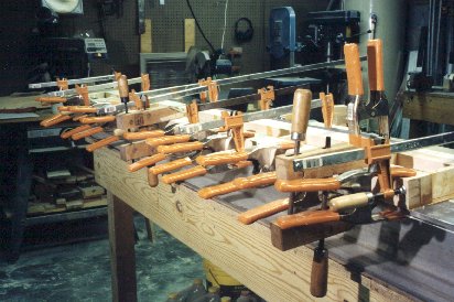
Here's where you may wish you'd bought more clamps. The final result is a spar that I have total confidence in. Notice the small test sample sitting on top of the spar. This is a piece of the spar cap left over when it was cut to dimension. You should mount the bottom half in a vice and break with a hammer, to see if the joint breaks or the wood fibers break. Make two of these, as your DAR (EAA Designated Airworthiness Representative who oversees your project as you progress) may want to break one himself.
Tapering the spars may be accomplished using a tablesaw, IF you use a brand new blade designed for plywood. Otherwise, you'll splinter the plywood faces to oblivion. Ask me how I know. You can also use a jointer set at an angle. Don't forget NOT to taper the part inside the cockpit. Also, stop the taper a few inches out from the fuselage, since this is the area of highest stress on the spars. The more spar cap material here, the better. The wing fillets will hide the extra spar material.
Outer Spars
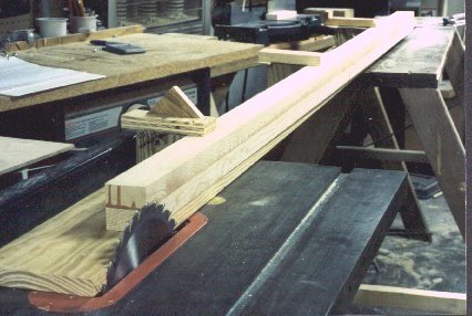
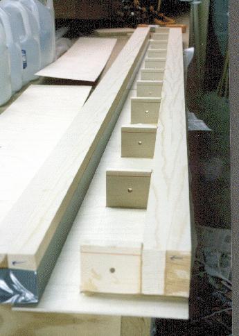
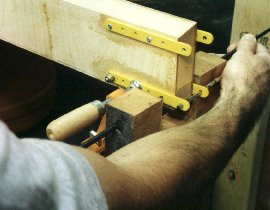
Construction of the outer spars is similar to the center spars, except that you need to taper the spar caps front to rear before you laminate them to plywood. I used the jig shown above to taper my spar caps. It's just a straight piece of 1"x6" with cleats screwed to it to hold the spar in place. Run the board through the saw shaving just a little off of the left edge and leave the fence in place. Now clamp your cap to it and the edge of the board is where the cut will be.
You can also adjust the table saw to cut the airfoil's taper while you're cutting the other taper. The yields a spar which requires no sanding whatsover, and a perfectly straight spar cap.
Outboard Spars
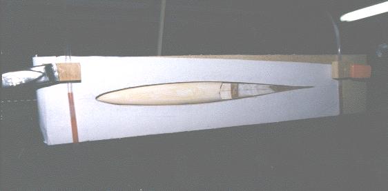
This picture shows the 4"x6" aluminum beam that I used to ensure that my spar components were straight and true. Here the spar was flattened while laminating to the plywood web.
It's a good idea to test fit all of your verticals and clamp everything together dry to make sure that you aren't in for any nasty surprises AFTER you've got epoxy all over everything.
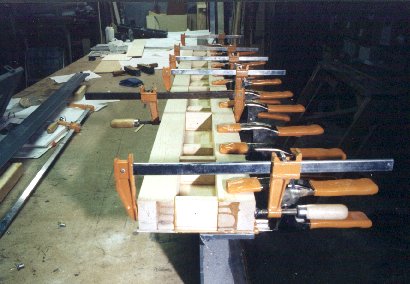
The spar cap is pressed flat onto the plywood, while the beam provides a flat surface beneath. Glue gap is maintained constant, and full contact is assured.
All that remains is to taper the spars on the outer spars. I've been waiting for the final details on the new AS5046 airfoil to determine the proper dimensions. Spars should be completed late this spring. I'll update this page when I get there.
Wing Attach Fittings
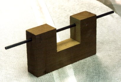
I whipped up this jig out of a piece of mahagony that I had left over from making Christmas present clocks. It is about 2"x4"x6" long. I drilled a hole through the block longways with a 12" 1/4" drill bit, and cut out a square hunk, then glued a 1' length of .250" OD 4130 tubing into the hole. After this picture was made, I hacksawed out the middle part of the tube to make the jig.
To use it, first align your wing attach fittings in place on the spar and clamp into place so that they are level with each other, and aligned with each other so that their holes line up. Don't forget to slip the lower pair out .125 inches or so for dihedral. Then just insert a long 3/16" drill bit or rod into the far end, and let it rest inside the wing attach fitting. Drill thru the other hole and you will go right on thru to push the drill bit out of the other side. I nailed 32 of 32 holes this way in the main spar.
One area of concern for the current KR2S plans is the lack of a standard horizontal reference plane, from which wing and tail incidence can be measured. After forming the "boat" by bending the sides to shape, the upper longerons become bowed into what has become known as the "banana boat". This in itself is no big deal, but you now you have no flat, level surface to call a reference. One solution is to use the local area of the longeron directly above and between the main and aft spars. As long as you use this same area as "level" when defining other critical angles, you'll be OK.
Personally, I defined "level" as being the upper longeron between the main and aft spars. Here's how to level your KR:
1) Longitudinal - Use a 2' level along the top of the upper longeron centered on the vertical member between the main and aft spars. Support the rear of the fuselage with a plywood brace underneath. I made mine out of two 6" wide 2' long pieces of scrap 3/4" plywood, formed into an upside down T cross section. Make sure it's long enough to support the lower longerons, rather than just the plywood skin. When this location is level, the spar verticals will also be plumb (vertical). Flip the level over and average between the two readings if they are not identical. This eliminates any error that your level may have.
2) Level the fuselage across the longerons with a four foot level laid across the upper longerons directly above the main spar locations. Use a builder's shim or equivalent to raise one side of the fuselage if it isn't level. Then recheck the reading obtained in 1) and correct if necessary.
3) Now that the fuselage is level in both directions, we want to make this configuration reproducible. Construct a water level from about 30' of 3/8 clear plastic tubing. Home Depot sells a nice polyurethane hose that is both flexible and clear (yes, I DO own stock in Home Depot!). Hold the tubing in a U shape, and add a few drops of red food coloring, then some water, then more food coloring, more water, etc., until the tube is almost full (maybe 8" of empty tubing on each end).
Pick some place that will be accessible after the plane is finished as your first reference point. I chose the top of the upper longeron at the firewall. Clamp one end of the tube here, such that the tube can be slipped up and down. I whipped up a holding block consisting of a 1x2x3/4 block with a saw kerf which holds the tubing in place. The holding block is clamped in place, and the tube can be slid vertically through it. Now take the other end of the tube back to the rear of the plane and clamp it to the fuselage at the rudder post. Back at the firewall, adjust the water level so that it aligns with the top of the longeron. Go back to the rear and make a mark at the same height as the water in the level. This is your second reference. Either drill a small hole, or put in a small nail, or something so that this mark will always be visible, even after construction.
You now have a reference level that is easy to reproduce. With the accuracy of the water level, a 1/32" deviation is easily discernible. Over the 147 inch distance from firewall to tailpost, this translates into an accuracy of .012 degrees. That's .04 degrees over the 4 foot wing root distance! When it comes time to install the wing spars and set the incidence, all you have to do is use the water level to set the fuselage up level again. You can use differential calculus (just kiddin') or basic geometry to calculate the amount of inclination from level that it needs to be set at. . If, for example, you want your wings to be 3.5 degrees from level at the root, get the tangent of 3.5 degrees, which is .0612, and multiply it times the length across which you will be leveling. In the case of the wing root, that would be 48 inches. .0612 x 48 = 2.94", so your trailing edge needs to be 2.94" lower than the chord line of the leading edge. At the tip, the tangent of .5 degrees is .000873, so .00873 x 29 = .253" lower at the trailing edge.
If you're living on the lunatic fringe and want to set your incidence at 1 degree at the root, with 3 degrees of washout, that would be .84 inches lower at the trailing edge, while the tip's trailing edge would be 1.5 inches HIGHER than the leading edge. Sounds crazy, but the airfoil is still generating lift at a negative angle of attack. If you opt for the 1 degree incidence, you will also have to adjust the horizontal stabilizer down a degree or so. Determining exactly how much is not a simple matter, so mine is adjustable so that I can nail it perfectly for my cruise speed after flight testing. For preliminary guesses, I used a simple fixture to hold the elevator straight and provide a chord line as a reference. It consists of a piece of 3/4" plywood 24 inches long with a cutout matching the cross section of the horizontal stabilizer and elevator at the tip. A straight line through the chord extends the full 24". The jig can be slipped over the end of the tail, holding the elevator in line with the horizontal stabilizer. You then have a longer chord line to measure by, yielding higher accuracy. After flight testing, since all angles and airfoil properties are known, I will be able to reverse engineer the combined aerodynamic properties of fuselage, canopy, cowling, and propwash. This may yield some interesting developments in the area of incidence and airfoils for future KR2S's.
When it comes time to set the dihedral, use the water level again between the root and tip of the outer sections. For lack of a good place to measure from, the bottom of the airfoil at the main spar is often used. In the case of the KR2, the tip is 5" higher than the root.
Return to the KR2S Construction.