KROnline September 1996
BUILDING A STRAIGHT KR FUSELAGE -- PART I
BY MARK D. LOUGHEED
Probably one of the most frustrating things about building experimental
aircraft, especially when starting with a minimum of pre-fabricated
parts, is to start building and ending up with an unexpected result.
Every builder starts a new project by wanting it to go "perfectly."
So when things aren't going well, especially at the beginning,
the frustration can lead to an unfinished airplane.
This is the first article in a series dedicated to helping builders
of the Rand Robinson KR series planes build a straight and true
fuselage -- the first part of the construction process. Borrowing
from modern boatbuliding techniques, focus will be on the KR-2S,
but the principles apply to the entire lineup of KR-1 & KR-2
series planes.
The problem (banana boat)
While building the KR-2(s) a common surprise is encountered by
builders when the completed fuselage sides are laid into position
to form the fuselage box section. With many hours spent building
the sides flat, finding the once straight longerons that now bow
up from the building surface, form a most dissatisfying "banana"
shape. Especially when using the preformed fiberglass parts,
this curve in the top longeron is not acceptable. The builder
is left wondering what went wrong and no amount of clamping or
brute force forming will solve the problem to any degree of satisfaction.
The problem is not the builder's fault. The solution starts
by understanding the three dimensional relationship of the assembled
parts being built.
First understand that the plans show the finished form of the
plane. They show the "projected" form as you would expect
to see it if viewing an actual plane from the top, ends and from
the side. Since the sides are sloped (flared) outward, looking
from the side, the distances given by measuring the profile drawing
are "foreshortened" and don't give the proper shape
for building the fuselage with a flat top longeron. What needs
to be done is to "develop" the "true" distances
and shape of the flat panel so that when it is curved into position,
the longerons lay flat.
Second, understand that the dimensions called for in the plans
put a twist in the sides that tends to work the panel in two directions
of curvature. This twist makes the panel "undevelopable"
meaning that that shape cannot be unrolled into an equivalent
flat shape. This is important when laying out the side and bottom
panels onto flat plywood. To illustrate this, try forming a
piece of paper around a soda can. The paper can be formed flat
around the can either straight or at a diagonal to it's length.
It has only one direction of curvature and is by definition "developable".
Now try to form the same piece of paper around a baseball. It
won't lie flat on the surface without some deformation (folding,
wrinkling or tearing) of the paper. The ball has curvature in
more that one direction and is a "compounded" shape.
Paper (or plywood) can only be readily formed in developable
shapes as opposed to aluminum or other metal which can accept
in plane deformation. A developable surface is needed to lay
out a curved surface when the materials used can't be deformed
with any degree of in-plane strain.
Initially, the fuselage sides are laid out flat with reference
to the top longeron measured to a straight chalk line. The bowing
problem starts when the side panels are bent and sloped to form
the fuselage box section. If the sides were not sloped (tumbled
home), the section formed would be cylindrical and the longerons
would lie flat. Since the sides are tumbled home, the section
formed is now conical. When a conical shape is cut with a plane
(building surface) not perpendicular to it's axis, the shape formed
is elliptical -- exactly what happens with the top longeron.
When it's built flat, bent to form a cylindrical section, and
sloped to form a conical section, it takes on an elliptical shape
firewall to tailstock.
The solution (new layout)
This method borrows heavily from proven techniques used in the
marine trades. It should be stressed at this point that although
the layout procedure is not complicated, it is important to take
your time. If the layout is not going well initially, start over!
Better to erase layout errors now than to have them built it
and cause surprises later.
Layout to ensure a fair and true fuselage starts by drawing a
reference line (baseline) on the building surface. Refer to figures
2 & 3 and use a wire guide to draw a very straight
baseline. About 500 lbs. Of tension should be adequate. One
could use a chalk line, but we're talking airplanes here, not
house framing.
The main layout difference is that the baseline isn't used as
a reference for the top longeron. The baseline references the
mid point of the firewall for the developed (and true dimensioned)
side panel. Although the baseline will still be the reference,
the top and bottom longerons will be laid separately.
Layout differences don't end there. Each of the stations (vertical
members) will be laid out with a calculated separation so that
when the panels are formed into position, they land on the spacing
called for in the plans. Another major difference is that the
bottom & side panels are applied after forming the fuselage
box section. This is mainly to obtain the ability to "fair"
the side and bottom surfaces and insure a straight and true shape.
Refer to figure 1 for the layout of the new developed side panel.
The firewall (station a) is layed out perpendicular to the baseline.
Longitudinal (station) measurements are given along the length
of the baseline from the firewall. Vertical dimensions are given
to reference the angle and breadths of the station at the baseline.
Notice that the top longeron is bowed outward and that the stations
are spaced slightly greater than called out in the plans. When
the panels are formed into the box frame section ,they will work
into the dimensions specified in the plans.
The layout itself (using the developed skin panel drawing)
It will be helpful to use a beam compass or trammels, when laying
out the side panels. A simple but effective beam compass can
be built by referring to figure 4
- Strike a centerline, longer than is needed on the building
surface using a wire guide. Draw off the firewall line perpendicular
to the centerline at one end.
- Using the distances listed in the balloons, mark them off
on the centerline. Distances are measured to the nearest sixteenth
of an inch. Take time to mark them off carefully. Don't mark
off the distances in a cumulative fashion. Use the firewall as
a common reference.
- Using the angles listed at each station, mark off a station
line longer than is needed. The angles are measured to the nearest
hundredth of a degree. Take time to mark them off carefully.
- At each station, start by marking off each short (bottom longeron)
line distance from the centerline. Use your set of trammels or
beam compass for doing this. Mark the intersection of the short
line with the station line.
- At each station, mark off each long (top longeron) line distance
from the intersection of the short line distance and the station
line. Again the trammels or beam compass is best for completing
this step. Mark the intersection of the long line distance with
the station line.
Fairing the longerons
Each intersection (top and bottom) marks the path that the longerons
will take. Lay out the longerons, carefully following the points
marked on the station lines. The ends of the longerons should
be run longer than is actually needed. Positioning the longeron
at each station can be accomplished by using batten holders made
for the purpose (figure 6) or by using lofting weights (called
"ducks" figure 5) or wood blocks. Remember that the
thickness of the longerons fall to the inside of the line. Sight
down the formed longeron. Take time to see and correct any unexpected
humps and hollows in it's shape. Remember that the portion of
the lower longeron should be straight from about station "i"
aft. The top longeron will be curved also. Removing the humps
and hollows out of the longerons is a time consuming and subjective
task. Taking time here will pay off in the form of uniform side
panels
Using the longeron as a batten, trace out the inside and outside
curves of the longeron. After the batten is secure, in between
each station, fasten a keeper block inside and outside to preserve
the shape of the longeron taking care to avoid potential future
interference with the diagonal members to be installed later.
The fairing blocks can be removed or left in place if they won't
interfere with building. The vertical station members and their
diagonals can now be measured and positioned. Remember to refer
to the plans for the material thickness direction.
After vertical and diagonal members are cut and fitted, take time
to draw their outlines on the building surface to cut down on
time and confusion when laying out the opposite side.
Finishing the side panel is accomplished in a manner similar to
that called for in the handbook with the exception that the side
and bottom skin panels will be attached later.
Next in the series (jigs, jigs & more jigs)
The next article in the series will discuss jigging and building
techniques to ensure alignment and straightness of the flat built
side panels. Also covered will be building a "strongback"
jig to assure alignment of the side panels when they are formed
into their final shape.
Part 3 in the series will cover assembly of the side panels using
the jigs. Some joint details will be discussed that will ensure
a stronger and more fair fuselage assembly. Also covered will
be the layout & attachment of the side and bottom ply skins.
About the author;
Mark D. Lougheed is a marine designer specializing in computer
modeling and lofting of commercial workboats and pleasurecraft.
With over 5 years experience in this specialty and over 10 years
in mathematics and computer related studies, he has lofted over
150 vessels from 12 to 210 feet. In addition to marine design,
mr. Lougheed enjoys applying his talents to flying and design
of experimental aircraft. He can be reached at;
E-mail: mdlougheed@wport.com
U.S. Mail: Densmore Associates, inc.
9594 1 St Ave. N.E., Ste. 421
Seattle, Wa 98115
Vox: (206) 528-6118
Fax: (206) 528-4717
Availability of scale prints
ANSI "D" size, computer generated plots of all the layout
drawings in this series are available from the author for $30
plus postage & handling. Full (true size) scale plots may
be made available depending on demand.
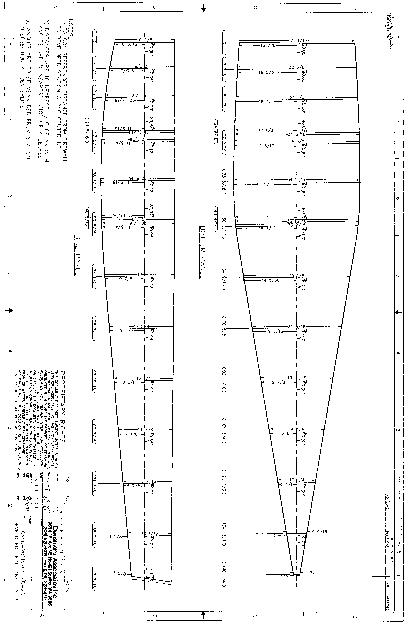
Figure #1 - Layout Drawing
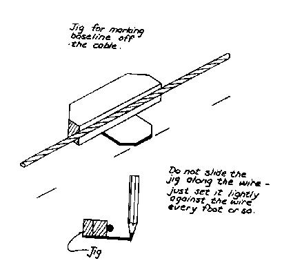
Figure #2 - Wire Guide
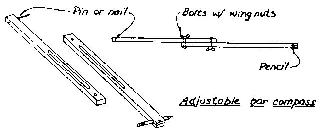
Figure #3 - Wire Guide Guage
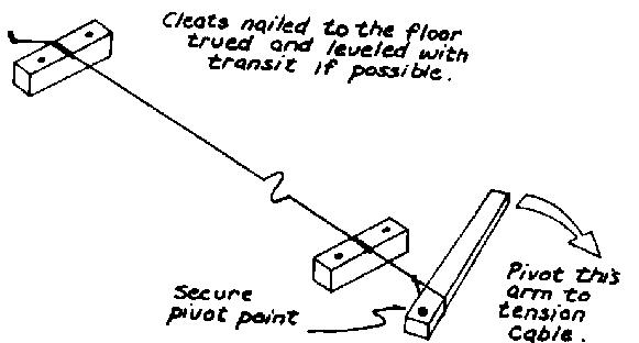
Figure #4 - Beam Compass
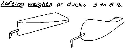
Figure #5 - Lofting Weights
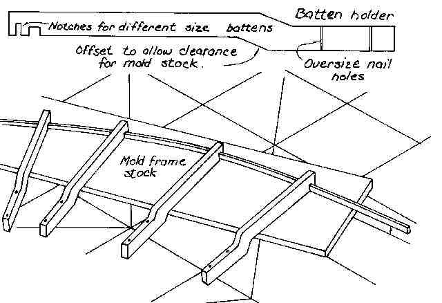
Figure #6 - Batten Holder
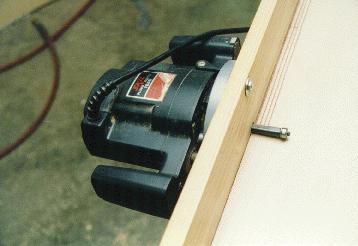
Router based plywood scarfer
"Scarfing" is the practice of splicing plywood so that
short pieces of plywood can be used to span long distances. On
the KR, it is required on both the fuselage skins and spar webs.
The angle of the splice should be 10 to 12 degrees to maintain
strength across the joint. Also, joints should coincide with structural
members, such as spar webs or fuselage truss members.
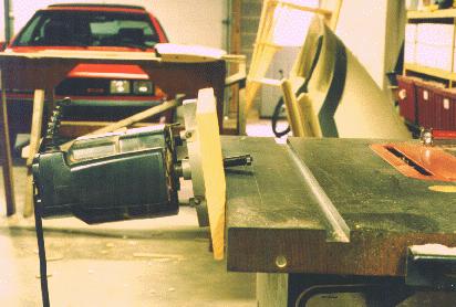
This scarfer is made by mating a regular plunge router (this one
costs about $50) to a table saw. Obviously, you really only need
a table saw to cut the chamfer, but it does make a nice heavy
table for scarfing. You could just as easily use a large work
table as the base.First, set the table saw for a 5.5 degree cut
(for a 1:12 joint, or 6.5 degree cut for a 10:1 joint), and run
a 1 x 6 through on edge to chamfer a corner on the board. Then
drill the board for three router mounting holes (two are countersunk)
and connect the assembly to the table saw with two 1/4 inch bolts.
Use a long (2-3 inch) straight cutting bit to do the cutting.
Adjust the bit so it doesn't interfere with your table top, and
go to town. Keep pressure on the plywood to ensure contact with
the table while you're scarfing. Make sure you feed your material
from the same end as you would if you were sawing, or the router
will take your plywood away from you and put a big dent in your
garage door.
As you can see, the joints are just about perfect, and they're
really fast to make. Once the fixture is built (20 minutes), all
of your wood can be scarfed in another 10 minutes. More tips
to come...including plywood cutting scheme (how to arrange your
birch and mahogony plywood cuts to maximize your wood, with proper
grain directions). - Mark Langford
KR Design History
In the late 60's Ken Rand and Stuart Robinson were working as
flight system engineers for Douglas Avionics. Ken was working
as an electrical engineer, having previously worked for Sperry
as an autopilots project engineer, while Stu's degree was in aeronautical
engineering from Northrop University. They were two of the guys
at the end of the DC-8,9, and 10 assembly lines responsible for
correcting some of the nits and picks in various systems before
delivery to the customer.
Stu had decided to build an airplane, and began looking for a
partner to share in the effort. Ken seemed a likely candidate.
He had grown up with the airplane bug, sketching aircraft designs
since childhood. He had been into R/C models for years, and had
already built a glider. He was a bit of a daredevil as well,
having done some time racing motorcycles in cages in Atlantic
City, among other things. No doubt who the test pilot would be.
They both wanted to build a fast, inexpensive airplane which was
also economical to maintain. Several designs were considered,
and plans were bought first for the Jeanie's Teenie and then the
Taylor Monoplane. The Monoplane was more to their liking, but
would require some modification to fit their needs. A cooperative
redesign effort ensued, with virtually no dimensions left untouched.
Only the basic fuselage structure, airfoil, and powerplant were
retained. The tail shape was Stu's, and came directly from the
big DC-8s parked on the ramp outside his office window. The landing
gear was designed by Ken, after seeing the gear on a Dewey Bird
at Santa Paula airport.
Construction began in 1968, with both Ken and Stu building an
airplane each. Stu was progressing faster, until he met a girlfriend
who would later become his wife. This development allowed Ken
to complete his airplane first, and it was registered N1436.
First flights were in the Spring of '72. Ken was a low time pilot
with only about 80 hours at the time, and had borrowed Stu's Curtiss
to get some taildragger (tailskid, actually) time. On the first
flight of the KR, Stu and three others flew chase in a Stinson,
but didn't get to see much of the KR1. It was much faster than
either of them had anticipated! That first landing was a real
greaser. It looked as though he had done it a thousand times.
Ken also flew to Oshkosh in '72, where his KR1 was awarded Best
Aircraft Application of Materials because of its composite wing
construction. Ken's and other early KR's used Dynel fabric rather
than fiberglass as the covering material. The composite wing
had been Ken's idea. Stu, being the more conservative of the
two, would have preferred a more traditional fabric covered wooden
wing.
Plans were offered for the KR1, priced at $15 a set. Popular
demand soon dictated a two place version, and the KR2 was quickly
designed. It featured a wider cockpit, almost two more feet of
length, and about four more feet of wingspan to handle the extra
load. The KR2's first flight was in April of 74.
Stu sold his interest in Rand Robinson Engineering in 1979, and
moved to northern California. He already had five acres of land
about 60 miles north of Yosemite, and felt it a more desirable
place to raise his children than L.A. He and his wife built a
new home, then he went on to build several more in the next few
years. He now works as an electrician for a large limestone and
dolomite mining operation, and is quite content with his move
Ken was killed in his KR2 a short time later while flying over
Cajon Pass in what was apparently a bad weather / low fuel accident.
Ken's wife Jeanette became owner of RR overnight, and stepped
up to keep the plans and parts coming. Much of the engineering
needs are handled by Bill Marcy of Denver, who's been helping
out since early '79.
To date, almost 6000 KR1, 9200 KR2, and 760 KR2S plan sets have
been sold. 1200 KR2s are estimated to be flying, with 5 KR2Ss
now in the air. Much of the development work done on KR's is
now done by the builders themselves. KR builders tend to be innovative,
which leads to some interesting modifications. Some of the mods
that work eventually creep into the plans. The KR2S is a case
in point. Many builders who'd heard of the pitch sensitivity
and tight cabin of the KR2 began to build an enlarged version,
with the length determined by the most commonly available longeron
material. The result is a KR2 that is stretched 2" between
firewall and main spar, and 14" behind the main spar. Higher
gross weights dictated more wing area, with the new standard becoming
the Diehl wing skin. Those who plan to carry passengers commonly
stretch the cabin width a few inches, although 1.5 inches is the
limit if you still want to use RR's premolded parts.
Asked it he would change anything in the KR2 design now that several
hundred are flying, Stu mentioned stretching the fuselage length
and height, as well as adding a little more wing area. Interesting
enough, that is exactly what knowledgeable builders have been
doing, and as the KR2S plans now reflect. He also thinks that
for planes flown close to sea level, that 2.5 degrees of wing
incidence is plenty. The prototype KR1 also exhibited a somewhat
abrupt stall, with the left wing dropping quickly. He would add
stall strips to the leading edge to soften the stall. Overall
though, Stu wouldn't change the airfoil. He is still amazed at
how well the prototypes flew, and mentioned that no changes were
made to the original plans after the initial flights. - Mark
Langford
Oshkosh 96 KR Forum
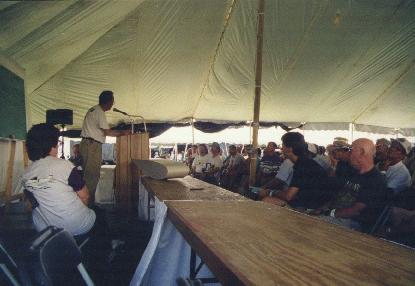
Mike Stearns addresses the KR Forum crowd.
This year's KR Forum featured guest speakers Mike Stearns, Steve
Trentman, and Bill Marcey. Mike Stearns spoke on several topics,
including the many sources for KR and homebuilding information
available on the Internet. He also mentioned KRNet, the list
server devoted entirely to KR aircraft, as well as several notable
World Wide Web home pages. He also brought a sample of the new
Rand Robinson wing skins with him, and discussed their high temperature
core prepreg construction. His KR2S will receive the first set,
which is currently being installed at Hinson Composites.
Steve Trentman spoke on his turbine installation. It uses a turbine
engine which saw duty as an A7 attack jet starter engine. Total
weight is about 85 pounds, while putting out around 90 horsepower.
There is a small stockpile of these engines available from government
surplus. sources. This engine can only be throttled back to 52%
power, which leads to some pretty interesting landings. One inflight
failure has been logged so far, with very little damage to the
aircraft. More on this exciting development in next month's issue
of KROnline.
Bill Marcey of Marcey Analytics spoke on the KR structure. He
has been responsible for much of the structural analysis that
has been done on the KR series since 1985. He spoke on seatbelt
installation, and firewall strength. He also mentioned that analysis
for the KR2S is still ongoing. Bill is very active in EAA, and
was award Volunteer of the Year last year. - Mark Langford
Les Palmer's N202LP
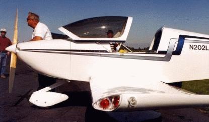
Les Palmer's KR2 N202LP won Best KR2, Best Engine Installation,
and People's Choice awards at the 1995 KR Gathering at Columbia,
TN. After researching the KR series, and reading Neil Bingham's
"A Critical Analysis of the KR2" (Jan 88 Sport Aviation),
Les decided to build his as a single seater, stretched 24"
in the tail, while maintaining a stock width firewall. His fuselage
is made from Douglas fir, which weighs in at 4 lbs heavier than
if constructed from spruce. It is skinned with 1/8" birch
plywood. Spars are covered with plywoood on both fore and aft
sides, ala KR2S. Diehl wing skins provide the lift. Horizontal
stabilizer and elevator were stretched 7" longer on each
side, while the vertical stabilizer and rudder were stretched
8" taller. . The fuselage to cowling junction was made more
graceful by adding 1.5 inches to the height of the firewall end
of the fuselage sides.
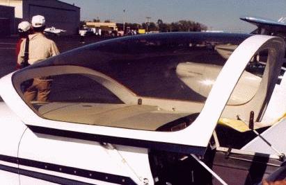
Les's canopy is a Dragonfly, using a four linkage system to swing
forward when opening. The canopy frame fits snugly into a recess
in the foward deck, providing an excellent wind and water seal.
The fiberglass work is exemplary.
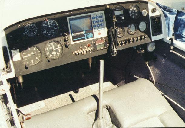
Seating is luxurious for one.
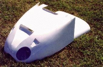
The cowling is also a work of art, and uses NACA ducts for efficiency.
Female molds were made for all the fiberglass parts on Les's
plane, so he could proabably be persuaded to make more, if demand
dictates. Les also machines a multitude of KR aluminum and steel
parts which he now offers for sale.
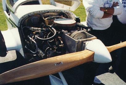
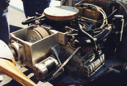
The firewall was reinforced with aluminum brackets and angles
bolted between the longerons in anticipation of the 200 lb Subaru
EA-81 engine installation. His 100 HP Asian version is outfitted
with an American Holley 5200 caburetor and manifold. It uses
a PSRU of Les's own design, featuring two spur gears with a 1.69:1
reduction ratio and a toothed belt. Other than tapping the crank
for larger bolts to mount the redrive, no other engine modifications
were required. Also, this is probably the only air conditioned
KR2 on the planet. The prop is a 60/63 Hegy.

Originally built as a taildragger, the fixed gear is made from
4130 steel tubing. Custom cast 6.00x6 aluminum wheels and steel
rotors are mated with 6" Cleveland calipers for braking.
An early taxi test accident damaged the main gear, and prompted
Les to change to tricycle gear. Again, he designed his own fiberglass
main gear, and uses a Diehl nose wheel fork with a 4130 strut
and 6" wheel up front.
Early tests revealed cooling problems, which prompted a radiator
move from the firewall to a lower cowling location.
The first flight was almost a disaster, as test pilot Randy Smith
lost power right after takeoff. He managed a 180 with a safe
downwind landing with only minor nosewheel pant damage. The culprit
proved to be a spark plug with too much reach, which was quickly
remedied. Subsequent flights have shown water temp to be about
210 degrees, oil temp is 220-230, and airspeed is about 180 mph.
Les can be contacted at: Les Palmer
3247 High Lark
Dallas, Texas 75234
Telephone: (214) 241-4387
Shopping for the Partially Built KR.
By: Jeff Scott
This story starts about twenty years ago when I first started
looking at the KR-2 as the plane I'd like to build. The only
problem at that time was a lack of money, lack of knowledge, and
a lack of job stability. I liked the design, except for the low
ground clearance of the retractable gear and that a KR was going
to be a tight fit for me to fly.
Over the past twenty years I've owned a number of planes, but
still always wanted to build my own. I needed one that would
fit me, my budget requirements, and have the speed and performance
that I wanted. When "KITPLANES" published the article
featuring Roy Marsh's new KR-2S, it was the first I had heard
of any major modifications or improvements to the same old KR
design. I believe that article and Roy Marsh's workmanship have
probably been the greatest boon to Rand Robinson (RR) in the last
twenty years. It certainly caught my eye! Here was the same
design I had decided I wanted to build twenty years ago, with
all of the improvements I wanted. It was sitting on fixed gear
with some reasonable ground clearance. It had the capability
to be built large enough to accommodate me. It has enough prefab
parts available that it didn't have to be 100% scratch built if
I decided to hurry the project along. And it had the speed I wanted.
I knew that Roy's published speeds were probably not realistic
expectations for the average KR, but after knocking around for
the last three years in my Champ, anything over 90 mph seems pretty
fast to me.
After purchasing the info kit and the sales video from Rand Robinson,
the next step after deciding for sure to build this plane was
to order the KR-2 plans and the KR-2S addendum. I finally got
my plans and was putting together my first order to start the
plane, when my partner in the Champ pointed out that there was
a partially completed KR-2S for sale in Trade-a-plane. My initial
answer was "No, I don't even want to look at it. I want
to build my own from scratch." My partner insisted that
for the advertised price and the fact that it wasn't too far away,
I ought to at least give the guy a call and investigate it. "No,
I don't think I want to buy someone else's problems," I persisted.
That night I went home and crunched up some numbers on the calculator
and finally came to the conclusion that for the sake of my budget
for the next several years, I really should give this guy a call.
Three days later, I flew to his place about 400 miles away to
take a look at his project. At this point I should probably mention
that I consider myself to be fairly knowledgeable about airplane
construction, although the vast majority of my experience is with
tube and fabric. The rest of this article deals with what I looked
for and more importantly what I missed and have had to repair
in the last year since I purchased the project.
When we went to the seller's house, I found that the left wing
was built using the Dan Diehl wing skins and the right wing skins
were leaning against the wall inside the house. Also the canopy
was in the house with the canopy covered with paper and tape.
I wanted to inspect the fuselage first, so off we went to the
shop.
There I found a fuselage sitting on it's gear painted in primer
gray. The first step was to inspect the quality of workmanship
of what could be seen as it sat. The interior of the fuselage
looked as if it had been built with a great deal of care. The
fit and finish of all of the interior wood was very nice. Even
the gussets looked like they had been painstakingly perfectly
fitted. The glass work on the turtle back also looked very precise
and clean. It was evenly faired into the vertical and horizontal
stabs. The tail also appeared to be well built with the exception
of a depression directly over the front and rear spars in the
horizontal stabs. He explained that when he moved recently, that
he had shot the plane with gray primer to protect it from the
weather since he wouldn't have ready access to a shop to put it
in right away. It ended up sitting out in the hot south Texas
summer sun for a few weeks before he got a shop rented to work
in. That caused the glass (or possibly the foam inside the horizontal
stab) to swell, except that it held onto the spar, so it was slightly
ballooned in front of and behind the spars. His recommendation
was to fill it back smooth with micro.
I also found a small linear crack in the lower left wing spar
cap on the left wing stub. It appeared to be from over tightening
the rear spar wing attach fitting bolts. His explanation was
that the crack wasn't important because the rear spars only job
is to keep the wings from folding back. I also noticed that the
holes for attaching the outer wing to the wing stub were badly
rounded out on the rear spar. He explained that the Diehl wing
skins require the rear spar to be swept slightly more forward
than the stock wings. This won't allow you to use the rear spar
attach fittings from RR and that I would need to fabricate a new
set of rear spar attach fittings.
I also found that the aileron bellcranks were not built or installed
as per plans, but found that they looked professional. I couldn't
check for function since the right bellcrank and sheeve wasn't
installed, the left wing also wasn't installed, and the right
wing didn't exist yet.
Next we pulled the inspection panels off of the fuselage and tail
and looked at everything I could see with a good flashlight.
I didn't find anything else that might be questionable about the
fuselage except for a cracked elevator trim tab that was damaged
when it fell off it's hanging place on the wall.
Next we spent some time going over his builders log and builders
photo album. I still hadn't seen anything that would dissuade
me from buying this project.
At this point it was starting to get late and my ride down needed
to get airborne for the flight home. I needed to make a decision
about whether I wanted this project or not, but I hadn't inspected
the wings and canopy yet. I took a cursory look at the left wing
and saw lots on micro built up on it and some bubbles in the leading
edge, but nothing that looked seriously wrong to my amateur eye.
The right wing was only a set of spars in the shop and the Diehl
wing skins in the house, so there wasn't much to look at there.
The canopy was wrapped in paper and tape, so there wasn't much
to look at there either. I decided that even if there were serious
problems in the wing that was built, I would be money ahead to
go ahead and buy the project. For the advertised price, I could
build a new set of wings and still be way ahead financially.
We negotiated a final price, shook hands, took my ride to the
airport, and started off in search of a U-haul to haul the project
home.
Now, at this point, some of you are thinking about what I surely
must have forgotten to inspect and why didn't I take a local A
& P or EAA member along for the ride. First of all, I don't
know any mechanics locally that have any experience with glass
and our EAA chapter of which I am VP is woefully lacking in fiberglass
knowledge. Secondly, as you will see, I missed plenty. Some
by ignorance, some by just not looking close enough.
Now for a list of the problems that I found over the last year
and a few of the fixes that I came up with.
I found that the lower set of rear spar attach fittings on the
left rear spar were installed backwards with the longer spaced
hole towards the fuselage. Since this is the same place that
also had the cracked spar cap, it required a major change. Also
in the same area he had drilled through the rear spar with a hole
saw to create a place for the aileron cable to pass through and
managed to cut out the second from the outside vertical brace
in the spar. Then he chose to install the aileron bellcranks
in front of the rear spar, and cut another hole through the rear
spar for the aileron push rod. He also managed to cut out the
outside vertical brace in the spar. Since the holes were already
drilled through the spar, the choices were to either cut out that
section of spar cap and scarf a new piece in, cut the whole rear
spar carrythrough out of the fuselage including ruining the left
lower wing skin, or do something else creative to reinforce the
spar cap and install a custom built set of attach fittings.
I also found that after I built and installed the right side wing
stub ribs and skin that the aileron bellcrank setup would not
work as installed. The cable that crosses between the two bellcranks
had a sharp uphill from the sheeve to the bellcrank in the last
12 inches on either side. This combined with the radius that
the bellcranks turn caused the cross cable to pull up tight when
the ailerons were pushed to either end of their travel, but allowed
the cables to go very slack when the ailerons were centered.
Also the Aileron pushrods needed to pass directly through the
lower set of rear wing attach fittings to attach to the aileron.
This whole rear spar and aileron bellcrank setup was going to
either have to be redesigned or cut out and built to plans. The
bottom line is that the problems I observed when I inspected this
part were much more serious than expected when I had to fix it.
I decided that I had to remove the rear fittings from the left
wing to be replaced with the new set that my neighborhood machinist
was cutting out for me. When I put the wing on the work bench
to start removing the rear fittings, I thought I had better take
a closer look at the bubbles in the leading edge. I found that
as I pushed on the leading edge, it delaminated between the glass
lay-up on top and the upper and lower wing skin edges that were
floxed together underneath. I concluded that that area had to
come apart and took a belt sander to the leading edge. What I
found was that the leading edge had been floxed together and glassed
over, but the mold release had never been scrubbed off the leading
edge of the wing. It peeled apart for rebuild quite easily.
When I got back to removing the rear spar attach fittings, I noticed
that the woodwork inside the wing looked awfully dull. The reason
was that the wing had been closed up without varnishing any of
the woodwork. This was rectified with a small hole saw, a number
of extensions and a modified undercoating sprayer.
I also found that the aluminum drain fitting in the bottom of
the left wing tank had been glassed into place upside down. The
tapered pipe threads were tapered the wrong way to install the
draincock into the tank. Retapping the fitting the right direction
seemed to be a good fix for that problem.
When I finally got around to attaching the wing to the fuselage,
I found that the front spar attach fittings were badly misaligned.
Although they could be forced into alignment, I didn't think
I needed that kind of preload on the main spar fittings. This
problem was fixed by calling on my local neighborhood machinist
to build me an aligning fixture and reaming the attach holes to
the next larger size and ordering the new sized bolts.
On the fuselage I found that although it had new Cleveland wheels
and brakes on it, one of the brakes had a severe wobble to it.
I must complement the manufacturers for taking care of that problem.
One call to the Cleveland factory and they shipped me a new set
of wheels and brakes even though the receipt for this set was
over four years old and in the original builders name. Their
only concern was that this set had never been placed in service
yet.
I chose to sand the load of micro off the left wing to see what
it was covering. When I got down to the glass, I found that there
was no glass for the aft inch and a half of the underside of the
wing in front of the aileron hinge. With the Diehl wing skins,
you build the wings, then cut the ailerons out of trailing edge
of the wing. He had mismeasured and cut too much material off
the bottom side of the trailing edge in front of the aileron.
It was filled by floxing a piece of spruce into the gap to fill
the space between the back edge of the fiberglass and the aileron
mount. I chose to wrap the trailing edge of that wing, and the
other wing to match with a couple of lay-ups of glass.
When I sanded the primer off the aforementioned damaged trim tab,
I found that the hinge was floxed to the leading edge of the foam
insides of the tab, but not the glass. I also chose to wrap the
front of the trim tab with a lay-up of glass.
I decided to pull the paper off the canopy and take a look at
it before I'm ready to bolt it on and fly. The original builder
had blown his own canopy and after some of the previous problems,
I was beginning to have some concerns about not having looked
it over closely enough. The canopy turned out to have been blow
a little too large. It ended up with a little larger bubble for
headroom, which I didn't object to. However, it had more headroom
on the right side than the left. Yes, it was just a little bit
lopsided. The main problem was that the canopy is stretched thin
enough that it can be easily pushed in with one hand when the
weather is warm.. My fear was that this is just thin enough that
it may decide to lay on my head or in my lap when flying on a
warm day. It will have to be replaced.
I'm sure that many that are reading this could see several of
the potential problems before I mentioned them, but some others
may not have and I'm sure that there could have been many other
problems that didn't but could have existed on this project.
This is also not intended to be critical of the gentleman that
started this project as many parts of it, especially the wood
work are better than I could have done and much of his work is
outstanding. I prefer to think that I'll end up with a better
plane with his woodwork combined with my glasswork. This article
is intended to feature some of the problems that you may run into
in buying someone else's project.
The final question is, knowing what I have found over the past
year, would I have still purchased this project. The answer is
yes, but primarily because the price was right in that I am still
money and work ahead of where I would be if I had started the
project from scratch. There are a few things that I would have
done differently, but nothing that I can't live with. Although
I won't be able to say that I built it all from scratch, I have
built and rebuild enough of the plane that I should have no problem
qualifying under the 51% rule.
You can send comments directly to the author via e-mail at "jscott@LANL.GOV".
Turtle Decks My Way - by Mike Mims
Here is an brief explanation of how I built my turtledecks. The
jig was constructed from scrap plywood and a few 1x4s that I ripped
into stringers. I made two temporary bulkheads from the plywood,
one for each end. Remember the forward bulkhead needs to be shaped
in a way that will closely match the aft end of your canopy frame.
Make an aft bulkhead by placing a straight edge at the top of
your forward bulkhead and the trailing edge of your horizontal
stabilizer. This will give you an idea of how tall your aft bulkhead
needs to be. As far as location, I placed my aft bulkhead just
forward of the lower/front of my vertical fin. I constructed the
jig on the fuselage, it is glued together with automotive bondo.
After the bulkheads were bondoed to the fuselage I used the stringers
that I ripped from the 1x4s and bondoed them to the bulkheads.
This gave me a male form to cover with thin plastic or posterboard.
I stapled two layers of posterboard to the jig(thin plastic would
work better). The posterboard wraps down two inches onto the fuselage.
After I was satisfied with the way it looked, I then covered the
entire thing with duct tape (fiberglass will not stick to duct
tape) On top of this I wetout one layer of tri-ply cloth (22oz)
that I had left over from an earlier project, and one layer of
8oz. bid. Remember to mask off your fuselage so you don't get
epoxy on it. If you are not familiar with composite lay-ups,
you should plan on razor cutting your lay-ups 4 to 6 hours after
wetout while the lay-up is still soft enough to cut with a razorblade.
After the lay-up cured (2 or 3 days) it was removed from the jig,
and the jig was removed from the fuselage and discarded. (be
careful, the bondo sticks very well to the spruce, you could splinter
your wood during removal) I now have a fiberglass skin that tends
to hold the shape of the jig but is still flexible enough to work
with. I made two bulkheads out of 1/4 last-a-foam (AS&S) using
the plywood formers from the jig as a guide. I covered these foam
bulkheads with one 8oz layer of glass on each side, with a glass
to glass edge on the bottom. After cure these bulkheads were bondoed
into place (to the fuselage)and the fiberglass skin was pulled
down tight and floxed to the bulkheads. When the flox cured the
bondo joints were broken, again being careful not to harm the
wood. The turtledeck was removed from the fuselage and 2 inch
tapes added to the bulkheads inside and out.
At this point the turtledeck looked great and only weighed about
5lbs. but I noticed you could deform the skin by pushing hard
on the outside. So I flipped the turtledeck over and from 1/4
inch last-a-foam, I cut two inch wide strips that would run the
entire length, forward and aft inside the turtledeck. In effect
these would act as composite stringers, I made enough of these
two inch wide strips to make up three stringers. One down the
center (sort of a backbone) and one on each side of the "backbone"
half the distance to the edge of the turtledeck. I sanded the
edge of the foam so that when covered with a layer of bid @ 45degrees
there would be a nice transition from the turtledeck skin up onto
the foam and then back onto the turtledeck I scuff sanded and
glued the foam stringers in with micro. I covered the foam stringers
with one layer of 8oz bid @ 45degrees.
The finished product weighs a little over 6 pounds and cost me
about $45.00!! When I decided to build a homebuilt I set a few
goals, they are to build a reliable, strong 2 seat aircraft, capable
of 200mph for less than $10,000. building a strong, light forward
and aft turtledeck for less than $100.00 will help in achieving
these goals! If you have access to the internet, please visit
my web site at: http://www.netcom.com/~mimsmand/mikeskr.html
(Netscape 2.x or greater recommended!)
You can also send me email at: mikemims@pacbell.net
if you have any questions or want to share your ideas.
KROnline is an online KR Newsletter devoted to sharing KR information with other builders and pilots in a timely manner. The first issue (September 96) is now available as a zipped MicroSoft Word file at http://members.aol.com/bshadr or as an html document at kronline9.html. If you'd like to submit articles or photos, email Randy Stein at BSHADR@aol.com
------------------------------------------------------------
Don't bother to email Randy though. KROnline has been retired since the KR Newsletter has improved.
Return to Mark Langford's KR2S Construction Page