The links above are provided for a direct link to each sheet. If you want to view them all, they are displayed below, in the same order.
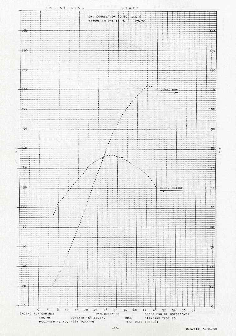
GM 110 HP and torque curve plots
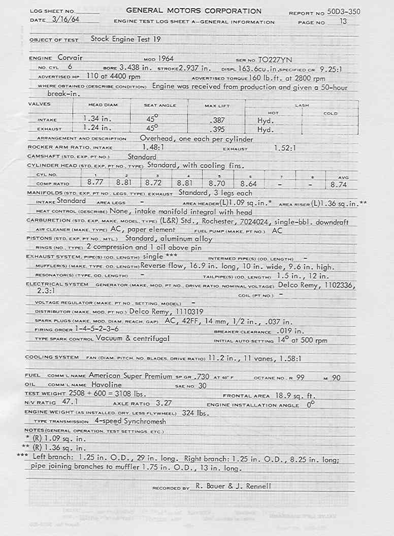
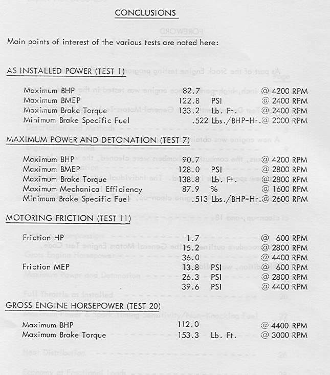
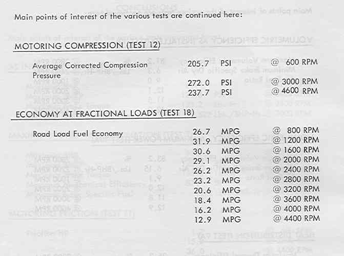
GM 110 HP test data sheet, as tested for the torque and HP plots
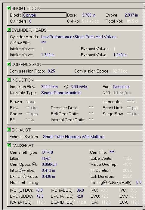
GM 110 HP technical data sheet 1
GM 110 HP technical data sheet 2
GM 110 HP technical data sheet 3
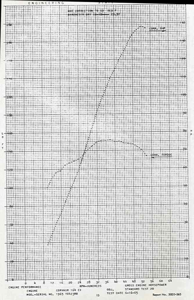
GM 140 HP and torque curve plots. Note that max torque occurs at a higher RPM, but is actually LESS than that of the 110 engine!
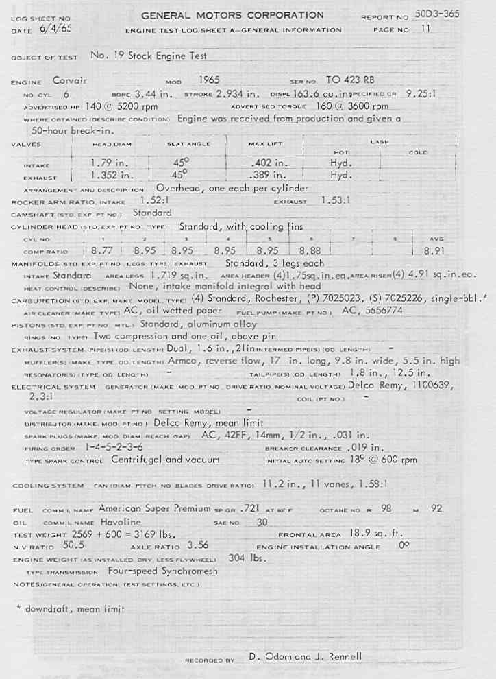
GM 140 HP test conditions for the above torque and HP curve plots.
Below are the cam specs for the OT-10 and OT-20 cams.
    int lift@ valve:    0.413
    ex lift@valve:    0.436
    ivo (btdc)    19.0    ivc (abdc)    63.0
    evo (atdc)    69.0    evc (atdc)    25.0
from which: lobe center-112.0; valve overlap-44.0; int. Duration-262; exh. Duration-274.0

For the OT-20: same except
int lift@valve    0.460
ex lift@valve    0.484
ivo (btdc)    25    ivc (abdc)    65
evo (bbdc)    72   evc (btdc)     32
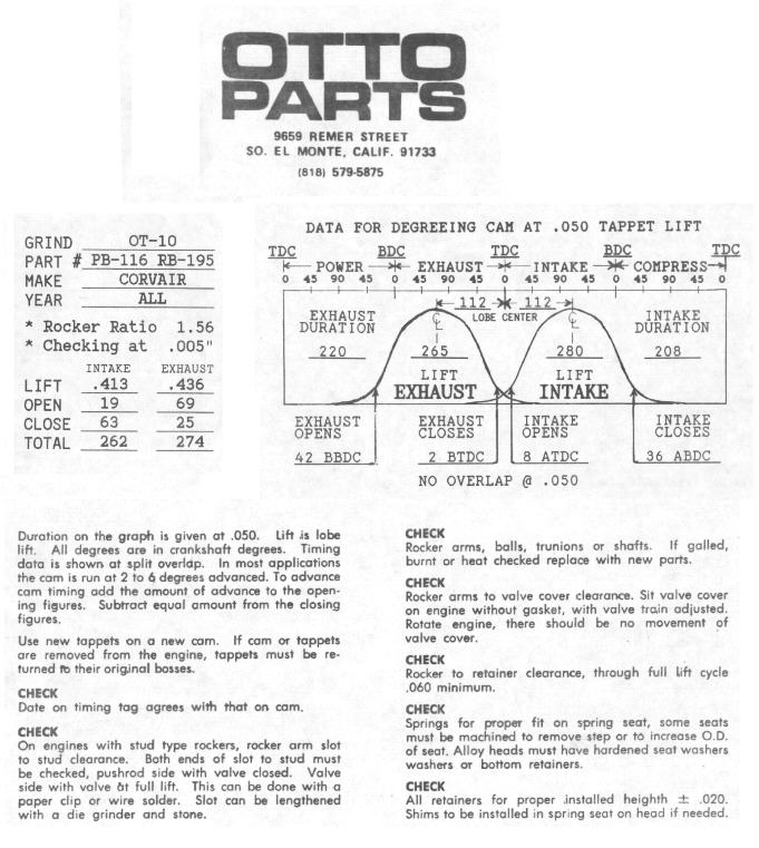
Cam tag for the OT-10 cam.

This is what Dyno 2000 thinks the output will be from a 3100cc Mighty Mouse with an OT-10 cam. This is setup I'm using, which uses stock 110 hp heads.
Here's the info that I fed it to get the above results.
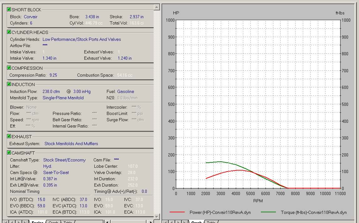
This is what it thinks of the stock 110, which is right on what the GM specs say, so I believe the results are pretty accurate for the 3100cc OT-10 version as well. Note the 110 hp at 4400 rpm! Just what the spec sheet says.

Here's a 2700cc (stock) bored .030" over with an OT-10 cam. Certainly no discernable difference with the over bore.
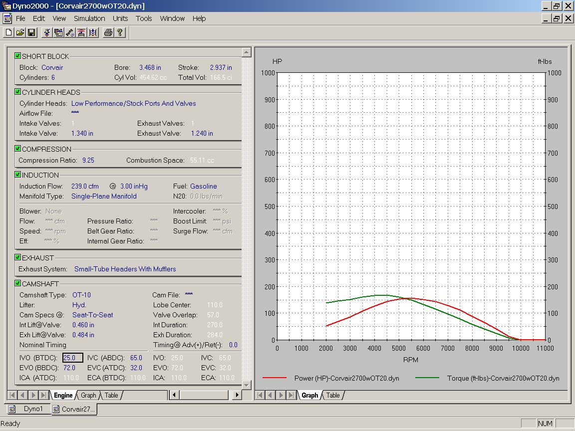
Here's a 2700cc (stock) bored .030" over with an OT-20 cam.
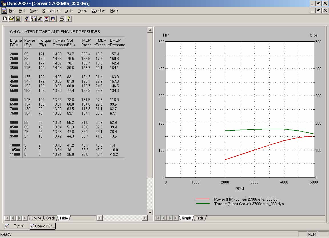
Here's a 2700cc (stock) bored .030" over with a Delta cam part number Del-319 from Delta Camshaft, 1938 Tacoma Avenue, Tacoma, Washington 98402, phone (1-800-562-5500)
It should be noted that none of this stuff is anywhere near gospel. I wouldn't even swear that the peaks of the curves are in the right place, because carburetion and exhaust can have a huge effect on where the powerband lies. Just use the above plots as an indication of the differences in different setups. Don't let them persuade you to do something that previous Corvair experience has already dismissed...
In December 2000, the CorvAircraft memebers debated what happens when your OT-10 cam is retarded 4 degrees. I ran the following scenarios through Dyno2000, all using the 3100cc "Big Boy" engine's parameters, which are nothing more than a stock 110hp Corvair with an OT-10 cam and increased displacement. I would expect similar results for the stock 110 engine using the OT-10, but yielding proportionally smaller numbers. Torque is green and horsepower is red. The following plots are rather informative.
Cam retarded four degrees with relation to the crankshaft (and all below are from also from crankshaft).
Cam neither retarded nor advanced.
Cam advanced four crankshaft degrees.
Cam advanced eight degrees.
Cam advanced ten degrees. This is what you'd get with a "retarded" automatic crank with the cam advanced one tooth (14-4=10 degrees). Torque at 3500 rpm is 194 foot pounds (the max available from advancing the cam), and hp is 129. This looks like the "hot ticket" to me. By the way, my OT-10 is a "rare" new one, rather than a regrind.
Cam advanced twelve degrees.
Cam advanced fourteen degrees, the equivalent of one tooth off. Things are starting to head downhill from here, if you need to spin a small propeller fast.
This is what you'd get if you RETARDED the cam by exactly one tooth. Much lower torque AND power.
Stock cam, no advance.

Stock cam, 6 degrees of advance
Stock cam, 4 degrees retarded.
Stock cam, 10 degrees of advance (4 retarded, but one tooth advanced!
The conclusions that I draw from the above plots are that something like 4 to 10 degrees of cam advance is perfect for MY engine at the RPMs I plan to run (cruise at 3400 or so). Not only is hp and torque higher than with no advance, volumetric efficiency improves from 78.2 percent to 84.7 percent (at 10 degrees). Now the question is, what is the downside? Obviously top end suffers, but we direct drive airplane guys don't care one bit about that, because we'll never get there. The OT-10 cam tag says that "for most applications the cam is run at 2 to 6 degrees advanced". That tells me that I'm on the right track, and that there's nothing wrong with going with 8 or 10 degrees of advance, if my application requires a strong bottom end. It also tells me that for airplane guys, one of those nifty offset woodroof keys good for 4 degrees of advance is certainly a step in the right direction. And if somebody told me I could gain 2% more torque by simply installing a $17 offset key between cam and gear, I'd be all over it. In fact I personally would do offset 4 degree thing if my cam gear weren't already installed using the "failsafe" method, and wasn't already sitting in the case.
The accuracy of Dyno2000's predictions with the stock 110hp Corvair leads me to believe that these plots are a true indication of the trends that one would expect by advancing the cam. Now, can anybody come up with a REAL downside that I haven't considered (something like overheating, which I wouldn't expect to happen, but...)
Below is the cam tag for the OT-10 cam.
Anybody ever notice how the lift figures are reversed between the specs to the left and the plot on the right? This worried me a bit, until I ran it through Dyno2000 and ascertained that it really didn't make much difference which one was which. Max difference was either one hp or one lb-ft of torque at 3500 rpm.
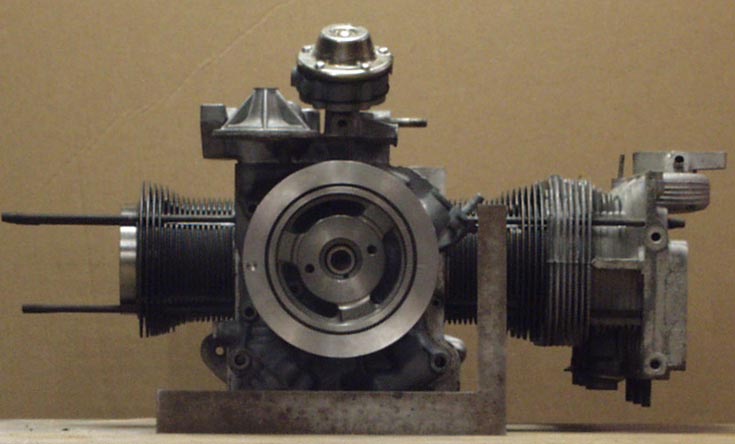
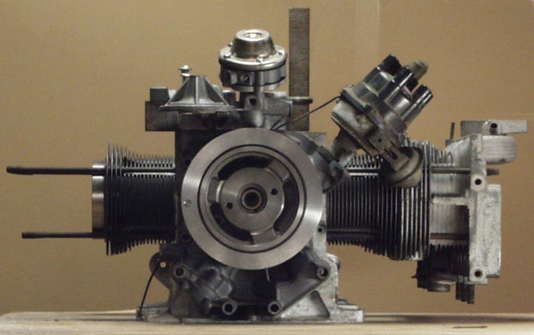
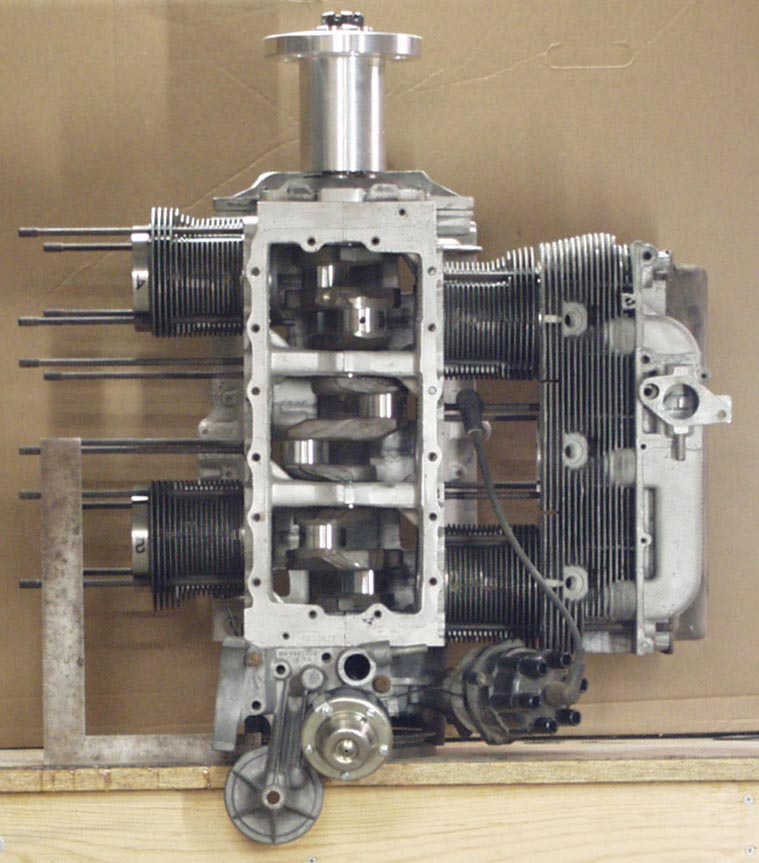
This and below are several photos taken at a distance (to reduce parallax error) that I used to obtain CAD views to help me design a cowling for my KR. The square is 12" long on one end and 8" on the other. In subsequent views there's a smaller one that's 8" and 6". I only bothered with half the engine since it's a simple matter to mirror one side to the other in the CAD program. I left all accessories in place, so that I could try lots of combinations of front and rear starter and alternator positions, leaving all options open.
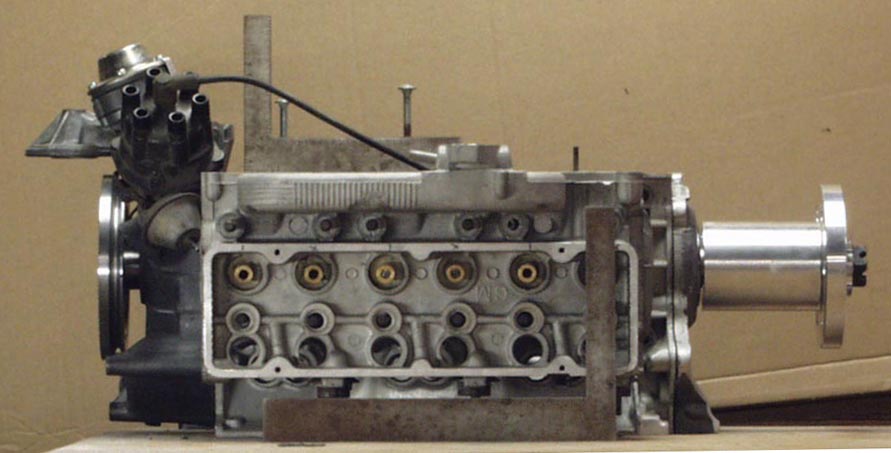
With my 5" long prop hub, the engine is 30" long, oil filter housing to prop flange front surface.
Everything below this line is stuff that I stole from the web and pasted in to help ya'll understand what's going on in the above charts.
-------------------------------------
CAMSHAFT TERMINOLOGY
A. LOBE PROFILE - The contour of the cam lobe which determines how far above the base circle a lifter is moved and for how long it is held off the base circle.
B. BASE CIRCLE - The part of the lobe profile that does not move the lifter up or down. (opposite of the lobe profile)
C. CAM LIFT - The maximum distance the cam profile will raise the lifter above the base circle.
D. GROSS VALVE LIFT - The total cam lift multiplied by the rocker arm ratio. (CL .280" X RAR 1.5 = GVL .420")
E. NET VALVE LIFT - Gross valve lift minus the valve lash setting for a mechanical camshaft. Net valve lift is not specified for hydraulic camshafts. (GVL .395" - VL .012" = NVL .383")
F. DURATION - Duration is the total angle in CRANKSHAFT degrees that a valve is open. Duration determines where the power range will be for a cam. Increase the duration and the power range will move up in RPM and you will lose low end power. DECREASE the duration and the power range will move down in RPM and you will lose high end power. What you gain on one end, you will lose on the other. To be useful, duration specifications must reference a lifter or valve lift. Advertised and .050" duration are the most popular durations used by camshaft manufacturers.
G. .050" DURATION - .050" duration is measured in CRANKSHAFT degrees from the point where the lifter rises .050" from the base circle on the opening side of the cam lobe to the point on the closing side of the lobe where the lifter drops to .050" from the base circle. The .050" duration is todays most common standard for measuring duration.
H. ADVERTISED DURATION - The point of measurement for advertised duration can occur at any lift above the base circle. The lower the point of measurement for lift, the higher the duration angle. This specification is provided for people who think more is better. Advertised duration is a duration stated by a cam manufacturer as a reference to their camshaft only. Advertised duration has no lift specification point agreed to among cam manufacturers. The same manufacturer may use different lift points on different camshaft profiles to list advertised duration. There is no rhyme or reason to advertised duration among cam manufacturers.
I. LOBE CENTERLINE - An imaginary line that goes from the center of the base circle through the point of maximum lift on a lobe.
J. INTAKE LOBE CENTERLINE - The number of CRANKSHAFT degrees from TDC (with the lifter in the middle of overlap) to the intake lobe centerline.
L. OVERLAP - Overlap is the angle in CRANKSHAFT degrees when both intake and exhaust valves are open at the same time. This is at the end of the exhaust stroke and the beginning of the intake stroke. INCREASING the duration will usually increase the overlap. Overlap must be specified at a lifter or valve lift value.
M. LOBE SPREAD or SEPARATION (mistakenly called Lobe Center or Lobe Centerline) - The number of CAMSHAFT degrees between the intake and exhaust lobe centerline of a given cylinder. This is the only specification given in CAMSHAFT degrees. The lobe separation is set when the cam is ground and cannot be changed. The smaller the lobe separation the more valve overlap. Lobe separation equals, Intake Lobe Centerline + Exhaust Lobe Centerline divided by two. (ILC 107 + ELC 117 divided by 2= 112)
N. CAM ADVANCE - To calculate cam advance you subtract the Intake Lobe Centerline from the Exhaust Lobe Centerline and divide by two. If you have a plus number then the cam is advanced, if there is a minus number then the cam is retarded. (ELC 117 - ILC 107 = 10 divided by 2 = 5, this cam is 5 degrees advanced).
O. .050" CAM TIMING - .050" timing is a reference point indicating where the intake and exhaust valves open and close. This is measured in CRANKSHAFT degrees at the point where the lifter rises .050" from the base circle on the opening side of the cam lobe, (valve opening reference), and the point on the closing side of the cam lobe where the lifter drops to .050" from the base circle, (valve closing reference). Note that these reference points are the same points that the .050" duration figures come from, only these are in reference to position of the piston in the cylinder near TDC or BDC. The specifications are given in the following form:
Engine Science
The four stroke engine is the backbone of the automotive and racing industries. Yet the basic scientific concepts of volumetric efficiency, thermal efficiency and mechanical efficiency and how they relate to engine performance is not well known.
It is pretty common knowledge among "car guys" that the pistons move up and down in the cylinders and that the valves open and close to create cycles. The four strokes (or cycles) that the engine uses are also common knowledge to car guys. This page provides you with the fundamentals of engine science and will take some of the mystery out of making more horsepower with a four stroke engine.
POWER SOURCE
Now, to the science part. Fuel has a chemical energy. A typical pound of gasoline contains 19,000 to 20,000 Btu. Just like 12 inches equals one foot, it is given that 2,545 Btu per hour = 1 horsepower. Therefore, the power output is directly related to how much fuel the engine can effectively burn. Now, don't run out and put bigger jets in you carb trying to make more power. If the fuel/air mixture is too rich it won't burn properly and you will make less power.
A better way to think about this relationship is that a larger engine would pull more air and fuel into the cylinders; therefore, a larger engine would make more power. Also, super charging or turbo charging packs more fuel and air into the cylinders, so this would also make more power.
VOLUMETRIC EFFICIENCY
Now imagine that this engine has some type of restricted intake, such as a small carburetor or restrictor plate like they use in NASCAR. With this configuration, the intake manifold has a fairly good vacuum. In this case, even though the piston pulls a volume of 100 cubic inches into the cylinder, it is not atmospheric air. Here, you have the 100 cubic inches of the vacuum from the manifold. You can think of this as the opposite of super charging because the cylinder ended up with less fuel and air molecules rather than having more fuel/air packed into the same volume.
Volumetric efficiency (VE) is used to describe the amount of fuel/air in the cylinder in relation to regular atmospheric air. If the cylinder is filled with fuel/air at atmospheric pressure, then the engine is said to have 100% volumetric efficiency. On the other hand, super chargers and turbo chargers increase the pressure entering the cylinder, giving the engine a volumetric efficiency greater than 100%. However, if the cylinder is pulling in a vacuum, then the engine has less than 100% volumetric efficiency. Normally aspirated engines typically run anywhere between 80% and 100% VE. So now, when you read that a certain manifold and cam combination tested out to have a 95% VE, you will know that the higher the number, the more power the engine can produce.
Basically, volumetric efficiency is effected by your carb, intake manifold, headers, and cam specs. All of these items effect how much fuel/air will flow into the cylinder. But remember, the more fuel/air that gets into the cylinder, the more power the engine will produce. This is where software programs such as Engine Analyzer Pro and Dynomation can be a big advantage. All of these programs calculate volumetric efficiency for different engine configurations that you enter into the software. This allows you to do your own testing without having to buy the parts until you get the right combination.
THERMAL EFFICIENCY
Compression ratio, ignition timing, thermal coatings, plug location and chamber design all affect the thermal efficiency (TE). Low compression street engines (smog motors) may have a TE of approximately 0.26. A racing engine may have a TE of approximately 0.34. Because these numbers are relatively small, at first glance there may not seem to be much difference between the street engine and the racing engine. However, when you grind out the math (.34 - .26 / .26), the racing engine produces about 30% more power because of the higher TE.
Finding little improvements to the TE can end up as a significant improvement to the final horsepower that the engine produces. Using the Engine Analyzer Pro software, you can try different compression ratios, coatings, etc. on your computer and see what happens to the thermal efficiency.
MECHANICAL EFFICIENCY
So, depending on how much fuel gets into the cylinder and depending on how much of the fuel gets converted to workable power, some of this power is used by the engine to run itself. The left over power is what you would measure on a dynamometer. The difference between what you would measure on the dyno and the workable power in the cylinder is the mechanical efficiency (ME).
Mechanical efficiency is effected by rocker friction, bearing friction, piston skirt area, and other moving parts, but it is also dependent on the engine's RPM. The greater the RPM, the more power it takes to turn the engine. This means the faster the engine runs the more the ME drops. Often times the ME is expressed in terms of friction horsepower. Or in other words, how much horsepower is needed just to overcome the friction. This is where computer programs like Engine Analyzer and Engine Analyzer Pro are fun to use because you can try different engine combinations in the software and see how much friction HP the combination creates.
------------------------------
email Mark Langford, at langford@hiwaay.net
INTAKE OPEN -5 BTC = before top dead center
INTAKE CLOSE 29 ABC = after bottom dead center
EXHAUST OPEN 44 BBC = before bottom dead center
EXHAUST CLOSE -10 ATC = after top dead center
NOTE: When a (-) minus symbol is used, then use the opposite heading. (BTC -5 = 5 ATC)
An engine is just a machine that converts fuel energy to a rotating motion, which is commonly measured as horsepower. In the engine, gasoline is added to the air as it passes through the carburetor (or fuel injectors) on its way to the cylinder. This mixture is then burned in the cylinder, creating heat which creates pressure. This pressure pushes the piston down in the cylinder to turn the crank shaft.
Imagine that you have a 100 cubic inch single cylinder engine. On the intake stroke, the piston moves to the bottom of the cylinder and creates a volume that is 100 cubic inches. The fuel/air mixture that fills this volume is what will be used to create the power.
Getting more fuel/air into the cylinder means more fuel energy is available to make power. Unfortunately, not all of the fuel's energy gets converted to rotating energy. Of the 19,000 to 20,000 Btu per pound of gasoline, typically less than 1/3 ends up as useable horsepower.
Volumetric efficiency identifies how much fuel/air gets into the cylinder and thermal efficiency identifies how much of the fuel gets converted to useable power, but some of this power is robbed by the engine's moving parts. It takes power to overcome the friction between parts and to run engine accessories such as the water pump.