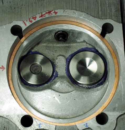
These .032" stainless steel valve shims are recommended (at least by Clark's who SELLS them) to reduce heat transfer from the heads to the the valve springs.
revised Feb 16, 2001
After solving several problems during "trial" assemblies I was confident that I could put it together permanently. It would be wise at this point to make sure that you don't plan to modify (such as enlarge or shorten) the intake flanges before you put it all together for the last time. Everything is cleaned one last time, either washed in kerosene and blown dry, or in the case of heads and case, blasted clean with the pressure washer and blown dry.
These .032" stainless steel valve shims are recommended (at least by Clark's who SELLS them) to reduce heat transfer from the heads to the the valve springs.
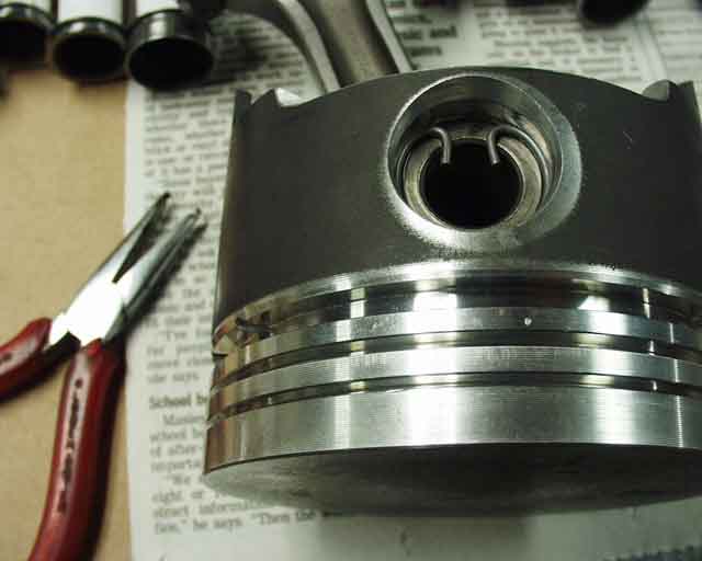
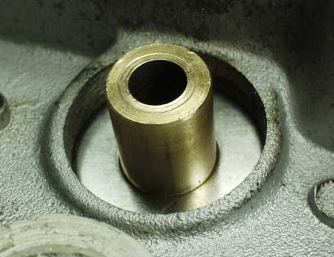
Connecting the rod to the piston is much simpler with Bob's big bore kit, since the pins are a close tolerance slip fit, rather than a press fit like the stock Corvair. Make absolutely sure that the circlips are seated properly by pressing on them with something to see if they'll move. If this clip isn't installed correctly, you'll score the cylinder when the pin finally migrates out to the wall.
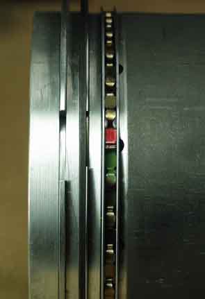
I used Total Seal "gapless" rings (Bob provides those as part of his Big Boy kit) as the second ring, a common practice in the VW world as well. It takes a little extrapolation, but the top ring's gap is at the bottom, the smaller of the second rings is also at the bottom, and the gap of the big second ring goes up. The oil ring spreader goes gap down (see green and red tabs) and the oil rings' upper and lower ring gaps should end up 60 degrees from the bottom, on opposing sides.
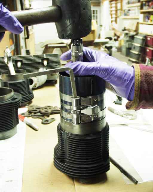
I lubed the ring compressor with nothing more than WD-40 (and left the pistons and rings clean), and whacked the rod a time or two with a rubber hammer to put the piston into the cylinder. Now I'll put these aside for a while and stick the case together.
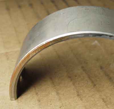
Now that the case, crank, and cam are all cleaned up, it's time to install the bearings into the case. Be advised that two of the 6 that "look" alike are actually different (one end is .0015 off center). These two will have a different part number on the back than the other four, and might have this copper "blaze" on one edge to further help identify them. I marked the edges red with a Sharpie so I wouldn't mix them up later. They go on the opposite end from the thrust bearing, and their locating tabs will force them to be oriented properly.
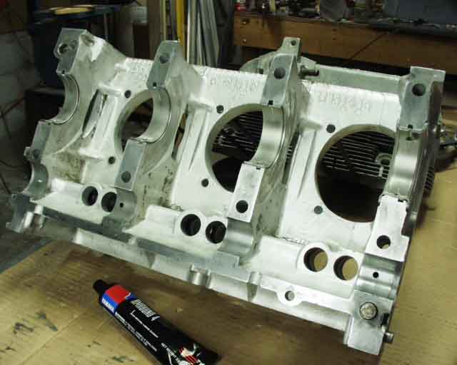
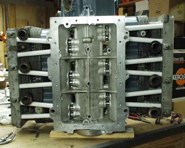
Here's the case with bearings installed.
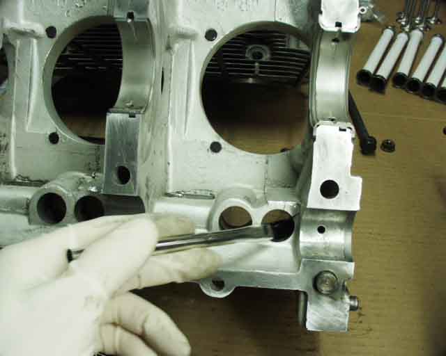
A mixture of Castrol motor oil and STP was brushed onto all the bearing surfaces and lifter bores before installation of the crank and cam.
The cam lobes were lubed up with moly grease designed for the high load job.
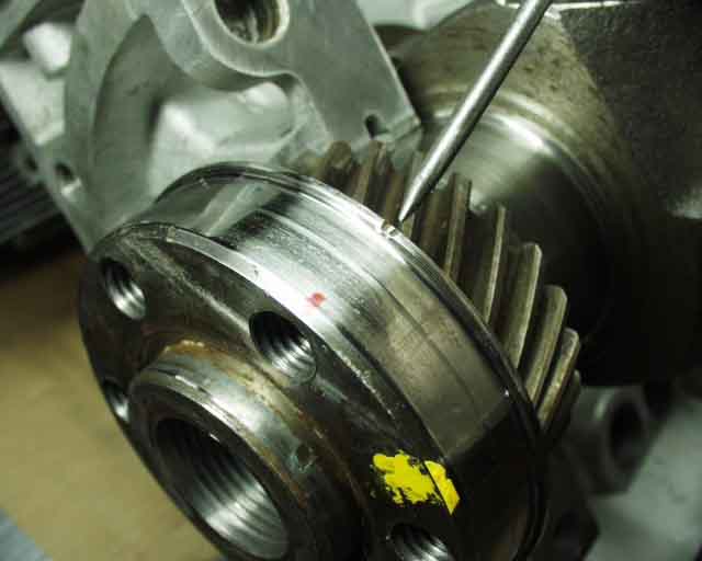
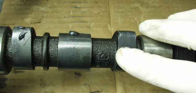
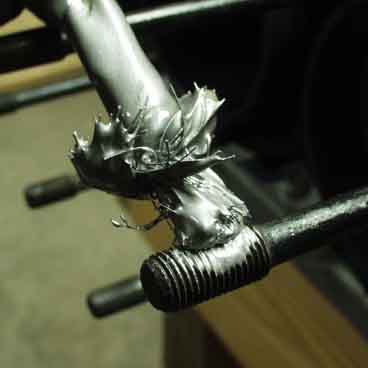
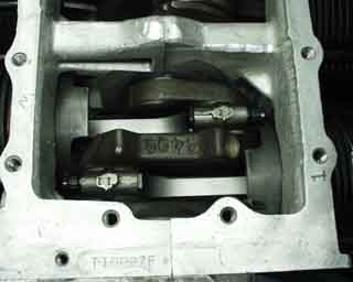
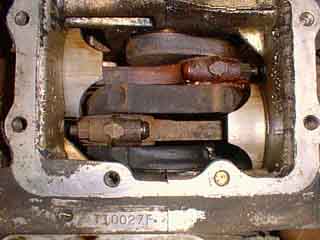
I took this opportunity to mark the crank gear and cam both with a red Sharpie to help align the timing marks, the two little notches. Given the fact that this just looks like impact damage from improper handling, I can see why it's not uncommon for people to time this thing wrong. I really didn't want to screw this up.
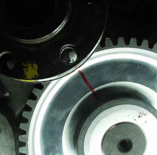
Here's the view of the timing marks when everything is hunky-dory. If you look hard enough you can see those two tiny notches on the crank gear's edge, but without that red mark you'd be hard pressed to find it! If you haven't seen them yet, please see my diatribes on determining your cam timing and how much cam advance is best for our airplane applications.
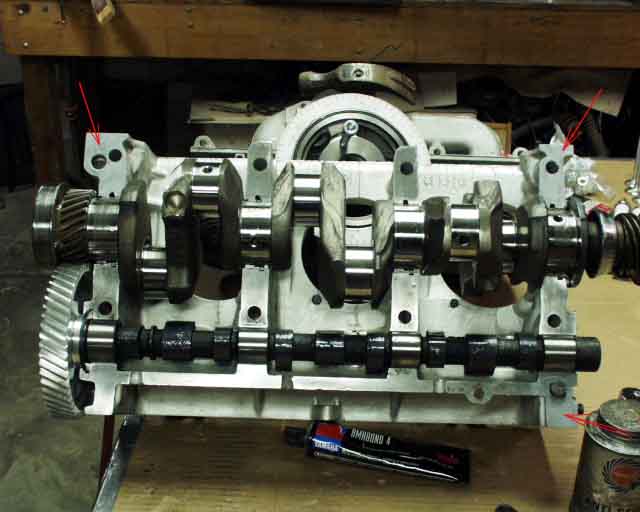
And a minute later I was ready to put the other case half on. I used Yamabond 4 (reputed to be the best for metal to metal joints in the VW world) at the three locations with the red arrows. If it leaks anywhere other than these three places, it's not going outside the engine anyway!
The bolts are torqued gradually, starting at 25 ft-lbs, then 35, 45, and 55, each time whacking the case halves with a rubber mallet and making sure that the crank still turns. You will be amazed at how much difference this "ajustment" process makes. And if when you finish, your crank won't turn, just loosen them all up and do it again. Next time it will probably be fine. You should be able to turn the crank easily with one hand, no problem. If you need a wrench or both hands, you better try again. Yes, I've torqued the case several times already, during the process of checking cam timing, Plastigaging the bearings, etc.
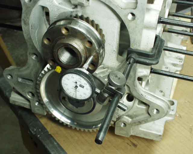
This dial indicator setup was used to check end play after torquing the bolts. I got .004", which is right in the middle of the .002"-.006" spec. Cam gear was checked as well, and was right on!
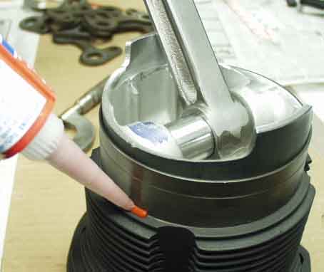
Now it's time for the pistons and cylinders. The cylinder bases get a thin bead of high temperature silicone to prevent oil leaks. Too much and the silicone could end up in places you'd rather it not be, like the bearings. This is the only place on my engine that I used silicone, mainly because it would be almost impossible for silicone applied here to end up inside the engine, especially in such a small quantity. You'll need to work quickly, since you have to install pistons and cylinders and the sheet metal below them, connect the rod caps to the crank, insert the pushrod tubes and make sure they seat, and torque the heads, all before the silicone cures.
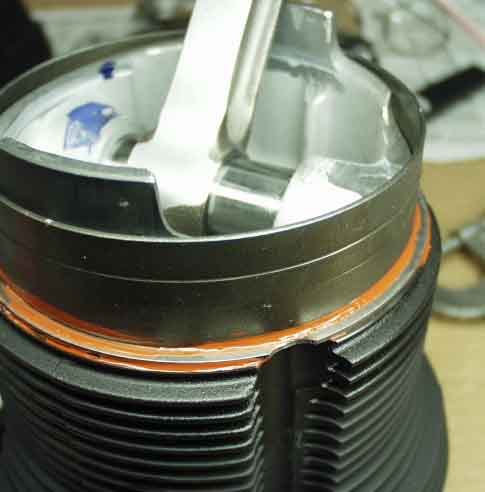
The cylinder shims are squished into the bead and another bead is applied.
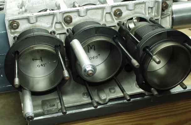
The pistons are slid into position one at a time and the corresponding rod caps are secured, but not yet torqued. Spacers and head nuts prevent previously installed piston/cylinder assemblies from sliding in and out as the crank is rotated, until the heads are put on. Note: This photo shows the arrows on the pistons facing the prop (flywheel) end of the engine, which would be correct for a VW or a reverse rotation Corvair, but for the normal CorvAircraft engine with normal rotation direction of the Corvair, they should be pointing to the harmonic balancer end of the engine. This is because the wrist pins are offset to minimize piston slap, so the arrows show which way they should be installed. Normally they face the flywheel, but not in this application! I figured this out before I ever flew, and installed them properly. After over 600 hours of flying, it appears that I was correct.
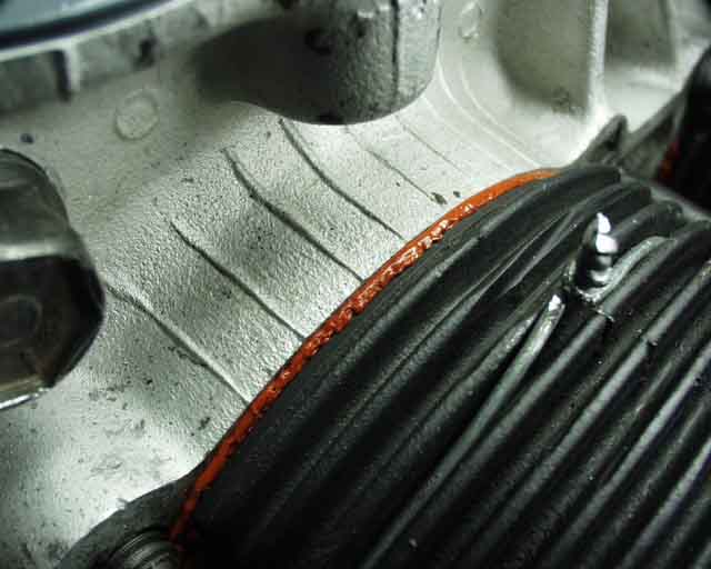
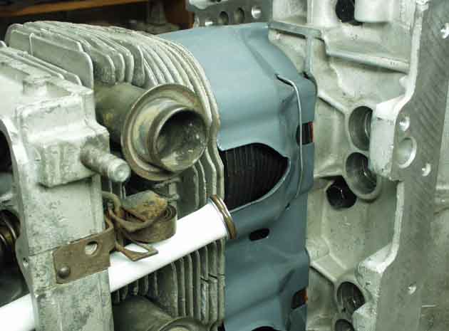
This silicone joint looks just about right. That twisted wire you see wrapped around the cylinder is baling wire. Yes BALING WIRE! Hey, this is Alabama, and I keep a spool of it around, just in case. This was the only way I could find to secure the lower cylinder shroud sheetmetal in place. They just wouldn't snap around the 94mm Mahle cylinders, although Bob said he had no problem with it. I guess I may NEVER be a REAL Corvair mechanic! At least this way there's no way it's going to come loose.
Now that the heads are ready to put on, it's time to install the copper head gaskets. These come in two thickness from Bob Sutcliffe or www.cbperformance.com, .040" and .060".
I applied antiseize compound to the threads to ensure that I wouldn't have any trouble removing them later. The use of anti-seize compound requires a lower torque, since the nut and stud are now lubricated. A good rule of thumb is to use 75% of the required torque, so I used 27 ft-lbs of torque rather than the 35 called out in the manual. If you use 35, you run the risk of stripping the nut or pulling the stud out of the case, which is not a pretty sight.
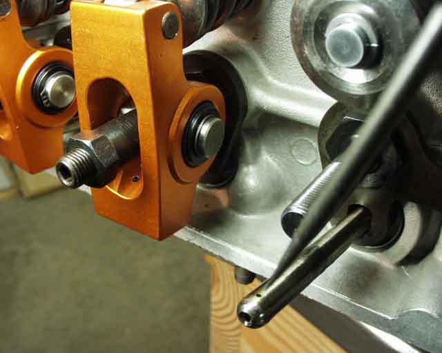
Next the pushrod tubes are inserted, already with the outer o-ring in place. The inner o-ring is placed after the tube is halfway installed, as shown here.
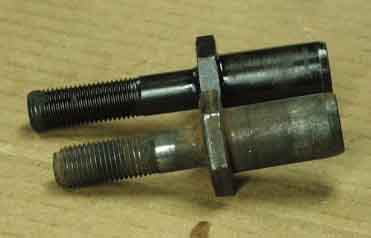
Roller rockers require slightly longer rocker studs.
I torqued the heads following Finch's recommendation of treating each cylinder individually, with a final torque of 27 foot pounds.
Pushrods are installed ensuring that the oil hole faces up, so that it sprays oil on the rocker for the first critical seconds of startup. It will eventually rotate to some other orientation, but it will do it's job at startup, at least. This strikes me as "lubrication by pot-luck".
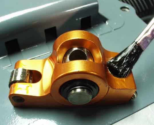
Here the roller rockers are pre-lubed with a concoction of 50% STP and 50% Castrol motor oil.
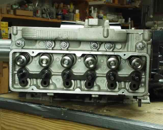
We're getting pretty close here.
Compare this one to the previous version of this picture! A slight improvement, wouldn't you say?
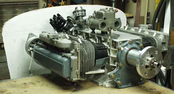
Now it's just engine mount and intake and exhaust manifolds. More later as assembly continues...
Return to Mark Langford's KR2S Corvair engine.