Mark Langford's KR2S Project
Horizontal Tail Construction
written May 15, 1996, revised August 2006...ten years later...
In an effort to tame some of the pitch sensitivity, a made my horizontal stabilizer 6 inches longer on each side, but adjusted the elevator area to remain about the same as the plans call for. Increasing the horizontal stabilizer area was an effort to increase the horizontal tail volume coefficient. The KR has one of the lowest of ALL airplanes, and since my fuselage was already built, making the tail larger was the only way to increase it to a more reasonable number. Were I to have the privilege of starting over, I'd make the fuselage about twelve to sixteen inches longer (by either adding an equal amount to each of the 8 bays behind the aft spar or by simply adding another 14" bay) so the horizontal stabilzer could be left with stock dimensions while obtaining the same result.
I also added two extra hinges (for a total of five) to effectively cut the hinge loading and wear in half. Having done this, I was later told that the Austrailian feds have been requiring similar modifications for the same reasons. I tried to make rod end bearings work for the application, but never found exactly what I needed. Dr. Dean did exactly that (see his elevator hinges) and that's how I'd do it if I were starting over.
For drag reduction purposes, I chose a NACA 63009 symmetrical airfoil for the root and the tip. That 5/8" square tip called out in the plans is certainly quick to build, but probably isn't the hot setup for aerodynamics. Of course we're only talking about a small percentage of total drag incurred, but it all adds up... I also think the higher lift coefficient of this 9 percent airfoil should also offer more control during a stall than the shape that it replaces, and it's a REAL airfoil, all the way to the tip. Not that there's anything wrong with the way a KR2 stalls, of course.
My first horizontal stabilizer was built the recommended way, using the long 3/16" rod to align the hinges, which were then marked, drilled, and installed. Unfortunately, once the rod is removed, the elevator removed, and you are able to get to the hinges to drill the spars for the AN-3 bolts, things move around sufficiently that your alignment evaporates. I supposed that the trick would be to lightly glue the hinges in place (just in case you have to replace them some day) while the rod is holding alignment, and later drill the holes using the hinge halves as your jig.
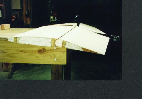
My second horizontal stabilizer was considerably nicer, but took about 60 hours to build. Yes, it will be a while before this bird flies at this rate. The new airfoils were plotted out full size with the spars (same 7" spacing as the plans) located on the plots. Then these plots were glued to 3/32" plywood which were cut out on the bandsaw.
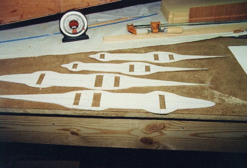
The "humps" around each spar were provided to allow the spar area to be cut away, so that the rib could also double as an alignment fixture during construction. Also, notice that the elevator and horizontal stabilizer are constructed simultaneously as one continuous piece, maintaining perfect alignment with each other.
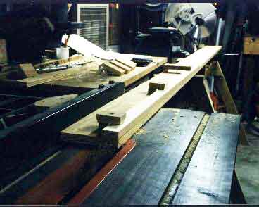
The tapered spars were created on the tablesaw with the same tapering fixture that the newletter printed a few years back. Simply put, it's a straight piece of 1x6 to which the spar is clamped using wooden clamps, at the desired angle. The angle on the blade was also gradually altered during tapering, so that the spars required no sanding to match the airfoil profile. This took an awful lot of thinking (mostly in mirror-mode) and ate up a lot of time, but was worth it in the long run.
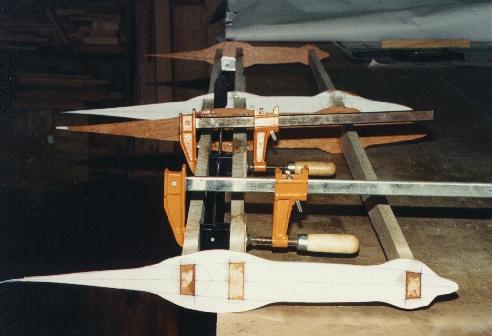
Once the spars were complete, the spar cutout locations in the rib/jigs were removed with a jigsaw. The spars were inserted into the ribs and properly located: the roots at 6" from the centerline, and the tips at the ends. With all the spars aligned and leveled (using a level, a waterlevel, and a straightedge) the hinges were again aligned using the rod and were clamped and epoxied in place between the two spars. All other joints between ribs and spars were also epoxied in place, and gussets added.
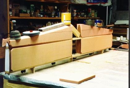
After curing, the humps were sanded off down to the airfoil outlines plotted on the ribs. 3" urethane foam (necessitated by my 9% airfoil) was then epoxied between the spars, and shaped by block-sanding between the ribs with an aluminum channel with 50 grit sandpaper glued to it. The large self adhesive sheets sold at Home Depot type stores for floor sanders works great for this job. The glass was applied per the plans, and the resulting surfaces are impressive. Elevator gap seals were created by sanding the urethane foam with PVC pipe covered with sand paper.
Most modifications have their compromises, and mine were no exception. Because my tips are airfoils rather than a piece of 5/8" square spruce, they are much thicker, and require deeper spars. That means they are heavier, but also stronger. But as we all know, the design doen't need to be "beefed up" anyway. The extra depth also required 3" thick foam between the ribs, but I simply glued some 1" to some 2" to make it, and ensured that the glue joint would not require sanding.
Not only am I using a different airfoil for my tail, but for my wings as well. And my wing incidence is set at 1 degree, with 2.25 degrees of washout. Obviously, the horizontal stabilizer incidence will also need to change.
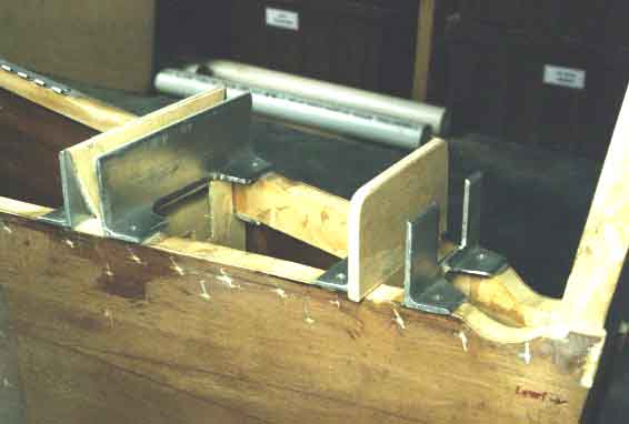
Since I'm using a main wing airfoil that hadn't been tested with this airplane [at the time I was building], I have made my horizontal stabilizer ground adjustable by adding a 2" x .75" .125" thick aluminum angle on each face of both horizontal spars connecting them to the longerons. This way I can fly the plane at cruise speed, trim it to fly level with no stick input, and land without changing the trim. Then, on the ground, I'll adjust the horizontal stab to reflect what the trim tab is trying to compensate for. By iterating on this procedure, I will eventually arrive at a point where my trim tab will be in line with the rest of the elevator, and my h.s. will be set perfectly for cruise speed with standard pilot and fuel. I will probably epoxy everything in place at that point for safety reasons, assuming no major CG altering modifications are foreseen. Looks good so far. I'll let you know how it works!
I've had a lot of folks ask me where I found the NACA 63009 and NACA 63005.5 airfoils that I used for horizontal and vertical stabilizers. Well....I cooked them up myself, using a program that Lionheart designer Larry French wrote that uses the NACA equations to create the points. If you'd like a set for your own use, you can download a 1200 dpi pdf file of the templates .
The file is only 120k, so it can be carried to a print shop and plotted out full size (42" x 15"). This file contains all the templates you'd need for rudder, vertical stabilizer, rudder, horizontal stabilizer, and elevator, plus rounded nose templates for each hinge gap. Note that you'd need taller horizontal stabilzer spars for these to work. This yields a stronger h/s spar.
Jan 2001 - Now that I've had a few years to learn more about things, if I were to build my elevator again, I'd probably use aerodynamic/static balance "horns" that both balance the elevator, and improve the airplane's overall stability. Dr. Richard Mole has designed just such a tail for the KR2S, which can be seen on Dana Overall's KR2S tail . Exact numbers have yet to be released for public consumption, but you get the idea. Just add some balance tabs. This sounds counterintuitive, but Richard Mole is an aerodymacist, and I'm at least willing to give it a try. I can always just cut them off and see what the difference is.
August 2006 - Several folks are now flying with these tail airfoils (including me), and by all accounts they work just fine. In fact, I have 300 hours on my plane, and because I have yet to add wheel pants or "finalize" the aerodynamics, I still haven't epoxied the horizontal stabilizer in place permanently. I guess that means it works. I'm still flying with the same -.75 degree horizontal stab incidence, and that's perfect with a passenger. With just me and full fuel, I need a little up trim dialed in, so I may try -1 degree of incidence, but I want to wait until all other factors are considered (such as wheel pants) before I do that.
Much later...2008 or so - I found myself always flying with the trim tab sitting about two LEDs above centered, so I finally dropped the nose of the horizontal stabilizer (it's adjustable, remember) another -.75 degrees, by sliding another piece of 3/32" plywood under the aft h/s spar as a shim. This centered up the trim tab nicely in normal cruise flight. I didn't expect any difference in speed since my trim tab is so small anyway, and there wasn't any discernable.
Return to Mark Langford's KR2S Project