Hinges
The hinges on the back of the KR has bothered me since the first time that I looked at the plans. I know, I know, "hundreds of them are flying like this," but that doesn't make it right in my book. In fact, if you look back through the issues of the KR newsletter and the archives of the posts to KRNet, there has been a lot written about the hinges.
First off, if any governmental agency comes out and says "you can build one of these airplanes, but you have to change the hinges" then you know something isn't quite right back there. The Australian feds did just that - they said that you must use 5 hinges as opposed to the 3 that the plans call out.
Somebody had written a question to KRNet about the use of Rod End Bearings for the elevator in the fall of 98. I always liked this idea, but nobody knew how to do it. There are rumors of various folks trying it, but few, if any, had made it work. I wanted to not only use the Rod End bearings, but I also wanted to put the hinge point where it is supposed to be - 1/2 the height of the elevator spar in back of the aft HS spar. Oh yeah, - it had to be cheap as well. The nice thing about Rod End bearings is that they are self aligning. As long as you use the same parts - the hinge point should always be at the same point between the spars, but if you're off a little bit (overtightening the bolts, or inadvertently angling something) the REB will compensate.
After pouring over catalog after catalog, I figured it out.
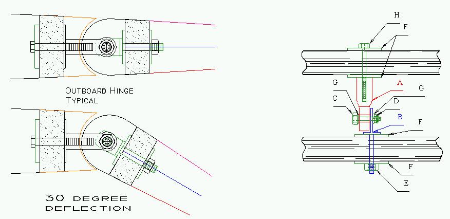
This is the simplest method that I could come up with. The nice part here is that all of the parts can be purchased from Wicks. What I have done is used a REB in combination with an eyebolt. The parts are listed below.
ELEVATOR HINGE PARTS LIST
| A | MW-3 Rod End Bearing |
| B | AN42-10A Eye Bolt |
| C | AN3-7 Bolt |
| D | Castillated Nut |
| E | Self Locking Nut |
| F | AN970-3 Washer |
| G | AN960-10 Washer |
| H | AN3-11A Bolt |
Now, as most people will using slightly different airfoils for the stabilizer and elevator the distance of the hinge point can be adjusted with the use of a spacer in the position of the washer behind the rod end bearing. For example - I need 0.040" between the rod end bearing and the aft HS spar, so instead of using a 0.063" washer, I will use a piece of 0.040" 4130 cut to fit. (I know, 0.023" doesn't really amount to much, but call me a purest.) I have also decided to go with 7 hinges in the back as opposed to 3 or 5. The reason is that since the hinge is not in double shear I would rather have more hinges to distribute the load. Besides, these things are light and inexpensive, so why not.
If you are building a KR-2S, I have heard that the spars in the horizontal tail use a 1/4" ply spacer. If this is the case, Part B needs to be a AN42-13A, and Part H needs to be a AN3-13A.
So now the question becomes "how do you do the control horn?" That's easy! I used a piece of 1" "T" shaped aluminum. The stuff isn't all that hard to find, and works like a dream. I just drew a picture of what I thought the horn should look like on the CAD, plotted out the templates, glued them on to the aluminum and made the part.
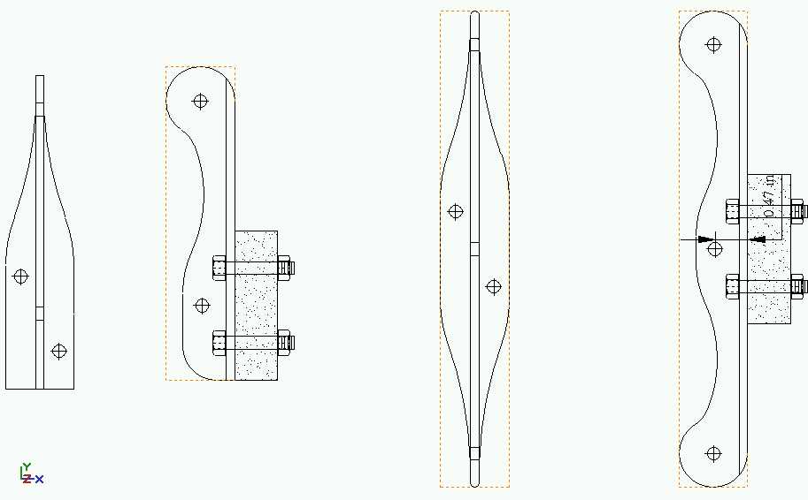
Sorry about the big pic - but it has to be that way to get the detail. There are 2 version shown above - one for those guys using a pushrod, and one for cables all the way back to the elevator. The critical part is getting the hole exactly 0.47" away from the back of the aluminum (where it abuts the elevator spar.)
I will be using the same type of hinge arrangement for the rudder, but I haven't gotten that far yet. (More to come.)
Dean R. Collette, MD
August 24, 1999