KR2S Fuel Tank Page
KR2S Fuel Tank Construction
created April 12, 1996...updated August 2006
Fuel tank/forward deck. My tank was scratch built using 1/4" thick 4 pound density Clark foam with two layers of 5.85 oz glass cloth wetted with Safety Poxy II sandwiched on each side. One 5 quart epoxy kit is all that is needed for layups and assembly. This was before I learned about vinylester, which is universally agreed as the one fuel proof resin that's best for fuel tanks.
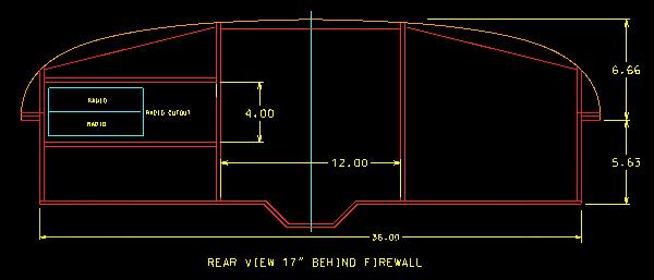
I modeled my tank in 3D on a CAD system in order to maximize fuel capacity, while providing ample room for instruments, avionics, and legs. I put my avionics cutout on the left side, because with a center stick, my left hand will be free to operate GPS and radios. Given my experience with the pitch sensitivity of the KR2, I don't think it's wise to try to fly one hands off. Originally, the fuel capacity of my design was 21.5 gallons, but after reflecting on the consequences of having that much "volatility" in my CG range, I decided to reduce it to 17.5 gallons. I may add a 6 gallon wing tank to the passenger side wing.
The first step to constructing the tank is to make a sheet of fuelproof "plyfoam" to make the tank from. Spray or brush a layer of PVA (poly vinyl alcohol, available from Alexander Aeroplane, Wicks, and others) release agent onto a quarter inch piece of glass that's already been waxed with mold release wax (like Partall). I picked up a 3' x 3' piece of salvaged glass for $15. Then lay up two layers of 5.85 oz fiberglass on top of the PVA, NOT being careful to keep the resin to a minimum. This is one place where excess resin is a good thing. Immediately micro one side of a large pice of Clark foam and stick it to the fiberglass. Squeegee the clean side of the foam to ensure direct contact between the micro'd side and the uncured resin/fiberglass. Then apply micro to the top of the panel and lay up two more layers of fiberglass, and squeegee again. The end result is a "plyfoam sandwich", with two layers of fiberglass on each side of the 1/4" foam.
Construction Templates
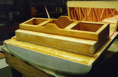
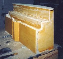
Decide on the shape of your instrument panel and draw a template for it. This is basically a mock instrument panel, and will extend to the outside of the two longerons, and will represent the outer shape of your forward deck. I made mine 7.5 inches taller than the longerons, with a nice elliptical shape, and it extends about 2" below the top of the longerons. Use the firewall template from the plans (or design your own more pleasing shape, like I did) as the front template for the tank. Once your templates are drawn up, cut out a firewall and instrument panel contour out of 3/4 inch particle board to be used as sanding guides, and clamp them in place. The aft end of the tank will be something that looks like a cross between the firewall and the instrument panel. If you make it a little large, it will simply be sanded to contour with the rest of the top of the tank.. The aft end of my tank is 17" from the rear of the firewall, which yields around 17 gallons of fuel, 7" of space for instruments, and 14" of space for radios.
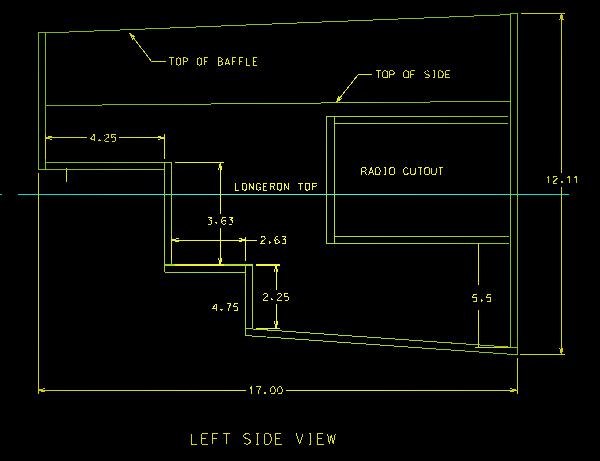
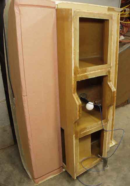
You also need two baffles for the interior. I made the bottom of my tank slope down as it goes aft, so that in a level or nose-up attitude, the fuel pickup will always be covered with fuel. There is also a sump in the center. This ensures that in straight and level flight, only about two ounces of fuel is unusable.
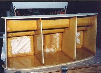
Position the foward end of the tank against the firewall, and the aft edge about 7" forward of the instrument panel. Cut out the two pieces which will sit on the two plywood firewall shelves and one which connects the two pieces together. Edge glue them together (with the smooth glass-like surface facing the inside of the tank) using flox and resin, and layup two layers of glass tape at each seam, overlapping in the corners. I used one strip of 1" tape, and one layer of 2" tape on top of that. The end result will be four layers of glass in each corner, with losts of resin to ensure against pinholes.
Install the two tank sides and the two baffles along with the aft end of the tank, edge glueing all joints with flox and resin and clamp lightly together.
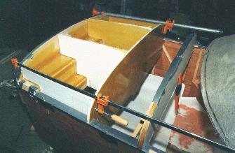
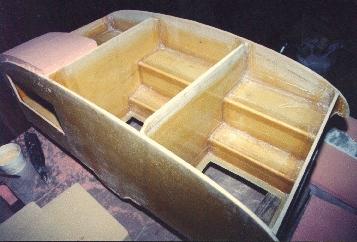
Here, the bottom is being temporarily installed while two more layers of glass tapes are used to create flanges between the side walls and the bottom. Peelply is used to prevent the bottom from sticking to the flanges. After curing, the bottom is removed so that the top can be constructed and sealed from the inside. Later, lots of resin is spread on the flanges, and the bottom is reinstalled permanently.
A view showing the bottom of the tank temporarily installed during flange creation. Duct tape was used during the process to hold the bottom tightly against the sides of the tank. No tapes are installed on the outside of the tank yet, but there's no reason why they can't be.
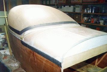
The top of the tank is constructed from two inch urethane foam, with the bottom side laid up with two layers of fiberglass on glass again, as before. It is then trimmed to fit into the top of the tank in three or four pieces. The fiberglass layer on the bottom of the foam should be a nice tight fit inside the top of the tank.
Flox them in place with a generous fillet in all corners. Then, working inside the tank from the bottom, immediately install the two fiberglass tapes around all joints again.. For mounting, I installed piano hinges between the longerons and the tank sides, where the two meet. The fuel tank is now removable by simply pulling the pins. Until these hinges are installed, the tank is actually resting on the ears of the front and rear tank walls.
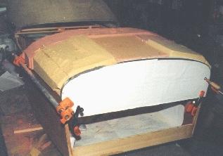
Sand the top of the tank to contour using a sanding block long enough to span both instrument panel and firewall plywood templates. Cover the longerons with duct tape to prevent damage to them.
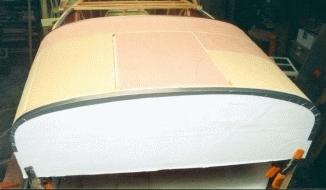
The resulting top surface is now ready to be 'glassed.
Lay up the top of the tank with one layer of 5.85 oz fiberglass cloth and one layer of fine weave 1.5 oz cloth on the outside. Squeegee on peelply over the tank top to absorb excess resin. After curing, use micro to blend the edges of the tank to the fuselage sides.
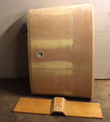
Install the fuel cap either forward or aft, depending on whether your gear is conventional or tricycle, and flox into place, reinforcing from the inside with fiberglass tape.
Install fuel sending unit. I used a universal VDO adjustable sending unit, part number 226-001, available for about $30.00. Don't forget to connect a ground to it. Ensure that there are passages at the top of the baffles on each end for air to pass through, and apply epoxy to any exposed foam. After installing the finger strainer in the tank bottom, epoxy the bottom on, and reinforce with the now familiar two layers of 'glass tapes.
You should now pressure test your tank with about 1 psi of pressure. Too much and it'll blow! You can use oxygen from your oxy/acetylene welder tank, because it has a very accurate pressure regulator. Yes, the area must be well ventilated.
Revision, later: Vinylester is the resin of choice for fuel tanks. It is almost completely impervious to most chemicals, including aviation and auto fuel. This is what I used to build my wing tanks with. It stinks, it's hard to work with, and I hate it with a passion, but it's the ticket for fuel tanks! One more thing I've learned is to make the tank panels out of 3 layers of thoroughly wetted-out glass. Or better yet, consider aluminum, which can be tested and then merely bolted in place!
Return to Mark Langford's KR2S Project.