Wing Construction
Stub Wing Construction
revised Aug 13, 1998
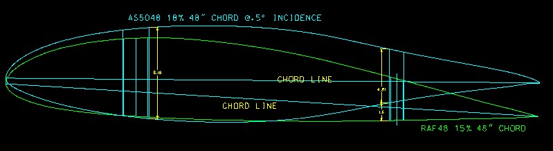
I'm using the "new airfoil", the AS5046, on my airplane. If you don't know the story behind this family of low-drag airfoils developed especially for the KR2S, you really should read about the cooperative effort that created it at http://www.krnet.org/as504x/". You can also find free downloadable full-size template drawings for them there, as well.
Stub Wing Skins
I cut my airfoil templates out all in one piece, leaving humps over the spars in order to ensure that the airfoil template/rib remained accurate.
After triangular gussets were glued to the template/spar junction, the humps were sanded away, leaving an accurate airfoil template.
I'm creating wing skins with a 3/8" thickness and glassed on the inside surface. This makes a very strong skin, and leaves more room inside the wing for things like fuel and controls, and it's much stronger. I'm glassing the inside with one layer of 5.85 oz glass, while the outside gets a layer of carbon fiber. I'll glass the inside surface first, and then flox the skin in place before sanding the outside to contour. When everything is in place, I'll sand the whole outside of the wing to shape. This way, the inside glass surface provides a very stiff support for the foam so that it doesn't deflect while sanding, yielding an airfoil shape that more closely resembles the templates.
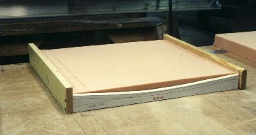
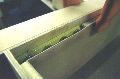
This sanding jig consists of two airfoil templates connected with 1"x2"s.
The foam is inserted.
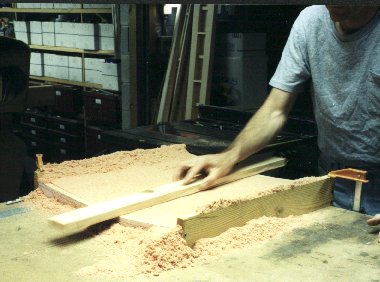
Two minutes later, your inside surface is sanded.
These surfaces will become wing tanks, so I covered each with two layers of 6 oz BID, soaked with vinylester resin. In order to eliminate pinholes, I squeegeed peelply over the glass with liberal amounts of resin.
I'm using vinylster resin because it is reputed to be fuelproof. It sure can be a pain to work with though. It smells terrible (ventilation is positively required!) and gets sticky just about immediately. This is somewhat similar to the stuff that you buy at Walmart (but it's polyester) to fix your boat , and is what most people think of when you say "fiberglassing". The temperature sensitivity makes the stuff on your hands (gloves) gel quickly, so that everything you touch sticks to you. Things like the glass strings around the ragged edges of your fiberglass cloth. Set down the bottle of catalyst and it sticks to you, so it falls over and pours out everywhere. Just keep in mind that it can set up quickly, and plan accordingly.
The tank sides were cut out of a sheet fiberglass/foam sandwich, which I made from 1/4" Lastofoam core with two layers 6 oz BID on each surface laid up on a sheet of glass. This yields a pinhole free surface that's smooth as glass. To make it, wax the glass, spray on PVA mold release, and lay up two layers of fiberglass on top of the glass. Then squeegee micro slurry into the foam, and squeegee the back of the foam to get the foam into contact with the glass. Now another layer of slurry to the remaining foam side, followed by two more layers of fiberglass and one of peelply. Let cure, peel away your new panel, and wash PVA away with water.
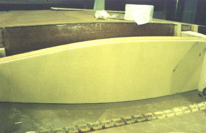
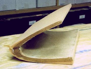
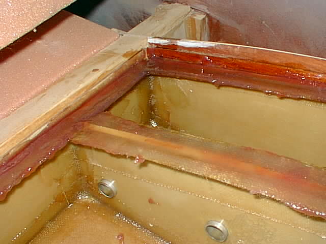
Since these particular wing skins will be the inside of a wing tank, I started with the top. Skin was protected by packing tape and positioned so that 3/8" to 1/2" of the skin was below the surface.
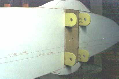
Clearance for wing attach fittings must be made in the panels which define the front and rear of the tank. Flox will potted around them prior to fastening the tank top. Side, front and rear panels were floxed to the spars and rib/templates, and flox fillets and glass tape applied to connect them all together. After cure, the top is popped back out, and the plane flipped over so that the bottom can be built permanently fastened in. After fuel lines, sending units, etc are installed, the top can be floxed back in place for a leakproof seal.
As usual, I'm doing things a little differently with my wings. Rather than the usual method of glueing 2" foam blocks in place and sanding and glassing the outside, I'm creating wingskins in place. This procedure involves a few more steps, but yields a much stronger wing surface. The end result is a skin that consists of an inner layer of glass (one BID), 1/2" of foam, and the usual number of outer layers (four on the leading edge, two every where else).
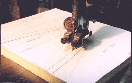
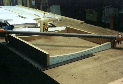
The first step is to create a sanding jig. I made mine from the airfoil plots, but with a 1/2" offset to the inside. I used spray glue to stick this plot to some particle board which was then cut out on the bandsaw. This cut isn't critical, since this is for the inside surface.
After making two of these, they were glued and screwed to a piece of 1 x 8 to create the jig.
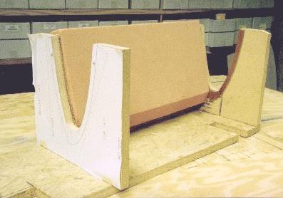
2" urethane foam is then glued in place in the jig.
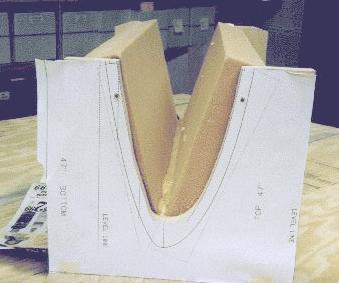
Hey, you don't think I'd leave out any details, do ya? Here's the other one lightly hot glued in place, with two part urethane foam (Wicks) in the joint between them.
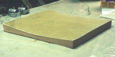
Well, OK, I left out a few details. I sanded the inside to contour with a piece of 1 x 4 with 16 grit adhesive backed floor sanding paper stuck to it. This is the resulting inner skin, with the outside roughly sanded to shape. Actually, the bottom is sanded to final shape for mine, since I did something pretty stupid (and you may too, if you don't think about it first). When using the Diehl gear, if you install the gear first and epoxy the leg to the mount (like the directions say) how are you going to sand the lower part of the airfoil to contour with that gear leg in place???? I dunno either, so I did it off the wing, being very careful to make it perfect. The little Mahogony strips you see in the previous photos ensure that I'll be able to line up the airfoil with the ribs. The inner wing skin was a big help too.
My point is, that were I to do it again, I'd NOT glue the fiberglass gear leg in place until AFTER the airfoil was sanded to shape. Then I'd slide the leg into place and glue and bolt into nutplates to the mount accessing them through the lightening hole in the rib. This is another one of those cases that nobody seems to mention that can make a difference in the performance of your plane.
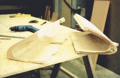
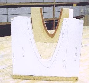
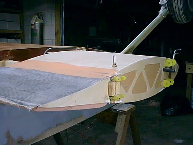
Here are both leading edges sanded to shape, with the left one clearanced for wing attach fittings, gear, and bolt heads.
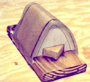
I also made a mold for my Plexiglas(TM) landing light covers. It was a ten minute job to make this thing, as I simply glued two airfoil leading edge plots (with a .08" offset to accomodate the plexiglas and fiberglass) to plywood and hot glued them to a 1 x 4 board.
I made the mold at least an inch wider than the light cover would be. I then filled with foam and glued it in place. 30 seconds of foam sanding and I was ready for two layers of fiberglass and peelply. Peelply is critical, otherwise the fiberglass weave will imprint onto the soft plexiglas (don't ask me how I know). After the glass cure, cover the mold with two layers of flannel or some similar cloth material. I used spray adhesive to stick it to the mold. Don't use too much, or it'll wick thru the material and mess up your light cover.
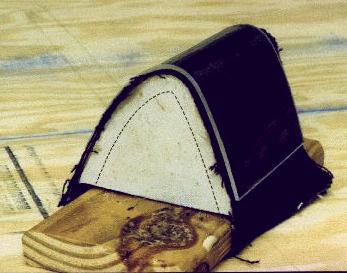
I set set the oven on 320 degrees and balanced the plexiglas on top of my little airfoil mountain. Came back in twenty minutes and it was sufficiently wilted over the mold to remove. There were still some residual stresses, so I used two oven mittens to press the plastic into close contact with the mold for a minute while it cooled (this is where you get the weave, if you didn't peelply). The result was some light covers that conform to the airfoil shape perfectly. As it cooled it contracted slightly, so now it's a tight fit over the plywood "cover mounts" that I glued to the rib.
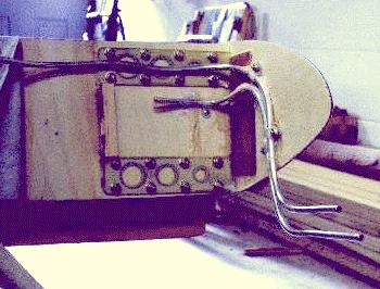
Here is my pitot and static tube installation. It's 1/4" soft aluminum tubing, and is much straighter in reality than this picture implies. Plastic tubing was safety wired (as a clamp) to the tubing.
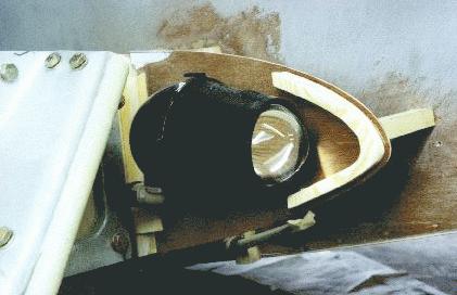
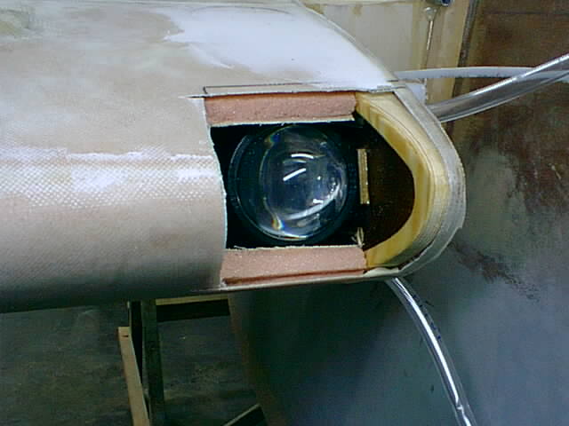
Here's one of the wonderful Walmart "Ultimate Laser Blazer Projector" driving lamps installed in my leading edge. I took the lamp apart and twisted the mounting 90 degrees so that it would mount from the side (to the rib), rather than the top. This also allowed the light to be moved closer to the leading edge, so a smaller plastic cover could be used.
Here's another view. Another reminder for "how you gonna sand the bottom of your leading edge to contour?".
Last night I glassed the bottom of my passenger side stubwing using the plastic sheet method. It went great and made the process much simpler. Tonight I sand the pilot's side and glass it as well. Then I'll be ready to flip the plane right side up again and install the wing tank covers and glass the tops of both stub wings. Then, it'll be outboard wing time! Spars are built, just need to be tapered and installed. I'll use the double skin method on them too. After wings, it's mainly engine and drive train and instrument time...
Thanks to my wife taking up my parenting slack, I've been averaging over 20 hours a week since I got the new airfoil coordinates. At this rate, I'll certainly be flying next year (1999).
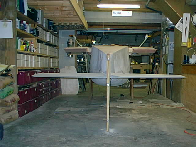
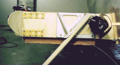
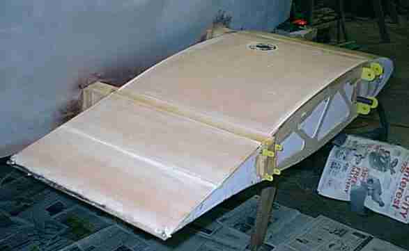
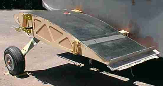
We flipped the plane upside down so the bottoms of the stub wings could be glassed, among other things. Yep, it IS standing on it's tail!
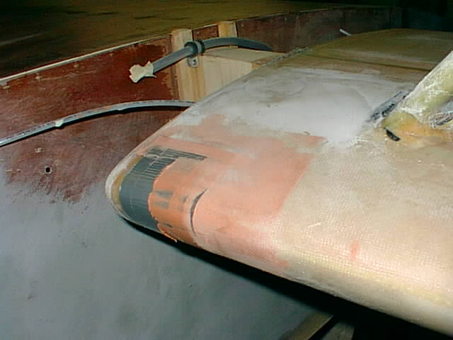
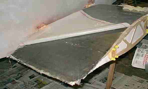
After sanding the bottom and leading edge of the wings to contour, two layers of glass were applied at a 45 degree angle. The trailing edge got two extra layers of carbon fiber in case some clown steps on it. The brass fitting sitting on top of the wing (actually the bottom) is a subtle reminder to me to install this fuel drain valve in to the bottom of the wing tank before closing out the top. It will be located in the trailing edge at the inboard end of the wing, so that water and contaminants can be drained during each preflight. During an annual, the whole fitting can be removed to drain the entire tank, if necessary.
After the glass cured, the landing light openings were cut out using the plexigl*s cover as a template.
The covers were slid under the edge of the fiberglass and floxed into place. The joint was then filled with this red Aeropoxy filler. This stuff works OK, but takes about 4 days to harden at 70 degrees. Micro is faster and works just about as well.
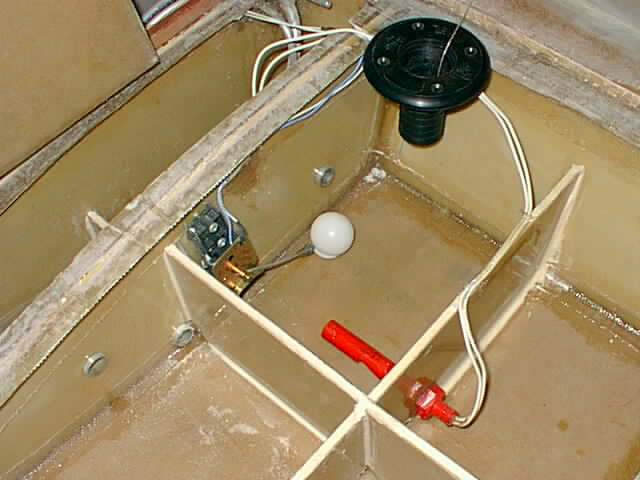
Jeanie and I then rolled the plane back over (it's easy rolling it over two sawhorses) to finish the wingtanks. I installed the red "low fuel level" sensor and prepared to permanently flox the wingtank tops into place. This low level light should come on when I have about two gallons left. I may also hook it to the auxillary fuel tank pump to start automatic refills. This is the passenger's wingtank which will serve as the main tank.
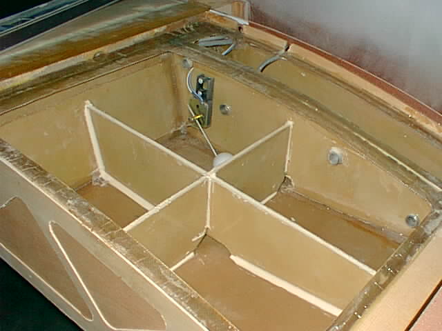
This is the pilot's wing tank, which will act as an auxillary "filler" tank.
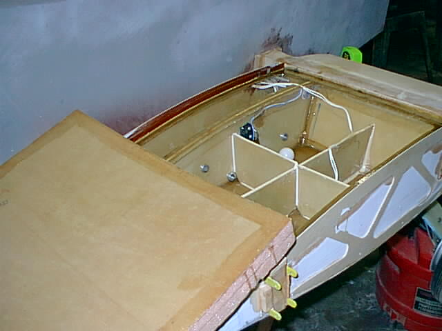
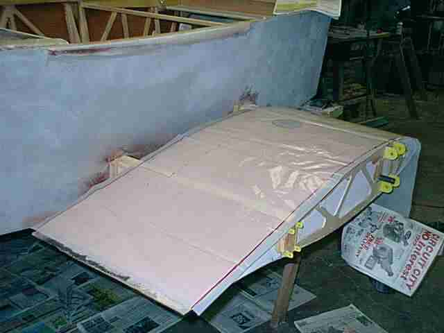
The edges of the tank top were sanded and primed, along with the "capstrips" that I'd built for the tank tops already.
Everything was mounded up with flox and the top squished into place.
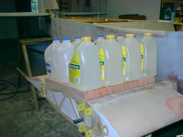
A little distributed weight and we'll check it tomorrow.
Now I'm just waiting on the carbon fiber to arrive from Wicks...
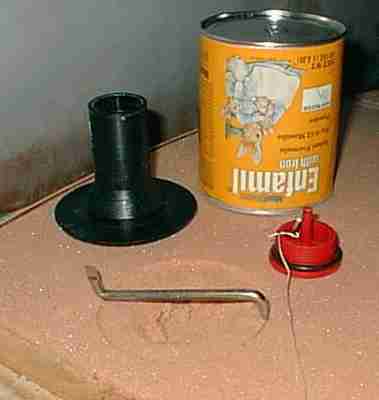
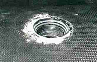
These fuel filler assemblies are from Great Plains and only cost $7 or so each. The catalog says fiberglass, but they sure look like plastic to me, not that it matters. The can was used to cut out a perfect circle to 1/4" depth the diameter of the flange. I used an offset screwdriver to hog out the 1/4' clearance for the "flush" mounting flange of the filler so that it would really be flush with the top of the wing.
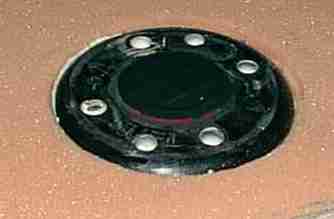
When it fit perfectly, I mixed up some of my favorite vinyl ester resin and made a mound of floxed mixture to squish the flange down into, sealing the top of the tank. I then mixed up runny micro and poured through the mounting holes just in case there was a leak, and to strengthen the mounting.
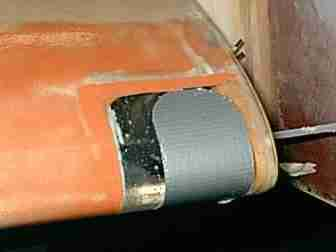
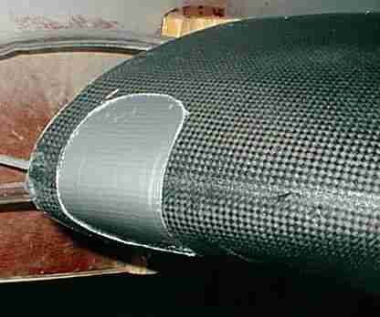
The landing light covers were duct taped over so that the skin could be flush, with only a cutout for the light to shine through. The orange filler is Aeropoxy's new one, which works OK but takes 4 days to become sandable in my 70 degree basement.
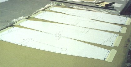
With everything laid out and ready to go, it takes three hours to lay up the top of each stub wing. I wrapped the two layers all the way around to the bottom of the main spar for a four layer leading edge. I used the polyethylene plastic trick (as usual) to make this go easier. First I cut out a sheet of plastic that was an inch oversize all the way around. This was then laid in position and the boundaries of the required layup were marked with a Sharp*e to define the required material size and the boundaries of the layup. This plastic sheet was then used to cut the material out at 45" angles to the rolls of glass and carbon fiber.
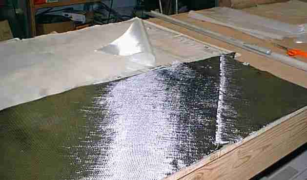
I laid the plastic face down and on top of it laid out the 1.45 oz/yd deck cloth which would serve as a pinhole eliminator. When you use this stuff you don't need to use peelply, and you get a small amount of extra strength. Next came the 5.85 oz/yd fiberglass cloth. Now was the time to straighten out all of the fibers so that they didn't wave around a lot. The carbon fiber was then laid out adjacent to the glass and its fibers straightened out as well. The plans call for only one BID of KR glass for the top of the wing, but since I have wing tanks, I wanted an extra level of safety so I used an extra layer of carbon fiber. This also makes it possible to walk on the top of the wing without any extra reinforcement.
Now it was time to squeegee on the micro slurry into the foam and all the cracks and crevices. The last .75" of the trailing edge had already been relieved of its foam, and that area was filled with flox for very strong trailing edge. After wetting out deck cloth and KR cloth, the carbon fiber was laid on top (the bottom of the layup) and wet out as well. Also, one additional 6" x 12" piece of carbon fiber was applied as a wing walk area starting at the aft spar and extending forward right next to the fuselage.
The plastic makes installing the skin a joy to behold. No wrinkling, and the fibers stay straight. After getting the skin where I wanted it, I squeegeed it into place and remove air bubbles with the plastic in place, peeled back the plastic and squeegeed everything into tight contact with the foam.
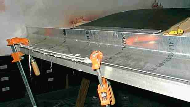
After covering the flox-filled trailing edge with skin, I smoothed a little micro over the top and clamped the whole edge between two large aluminum angles to ensure that it ends up straight and strong.
After applying the skin (but before it set up) I cut out the fuel filler holes by inverting a small glass over the caps and cutting out the circular chunk of skin.
The landing lights got the same treatment, yielding a flush installation with no drag-producing joints. Of course, I can't get in there ever again either...but I can replace the bulb thru a small access hole in the bottom of the leading edge near the spar. The angles of the lights can also be adjusted through the same hole, should that be necessary. The final step will be to make another duct tape cover slightly smaller than this one to protect the pl*xiglas, and then micro between the exposed acrylic and the skin. It'll be ready to paint then.
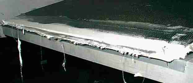
The trailing edge won't require much cleanup work, since I spread a little micro under the aluminum angle before clamping the top angle to the bottom angle. A few minutes of cleanup work and it'll be done. The bottom won't require any cleanup work at all.
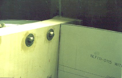
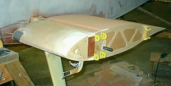
Here's the final result, in AS5046 airfoil form. The extra plywood in the rib is the former NLF(1)0115 template, which also serves as my wingtank endplate, so I had to leave it in place and add the AS5046 with lightening holes on top of it.
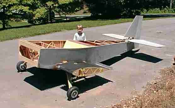
Here it's sitting out in the sun in the driveway getting an "oven cure", mostly to finish curing the vinyl ester resin that I used to install the wingtank tops a few days ago. It seems that the new batch of vinyl ester that I got from AS&S doesn't set up nearly as fast as the gallon that I used to construct the tanks from originally. The 1% MEKP catalyst that I used was still not fully cured two days later in my cool basement, so this will probably finish the job. Maybe the first batch that they sent me was "over promoted", which might explain the bad taste it left in my mouth for vinyl ester.
Next, the OUTER WINGS!!!!!!!! Spars are built but need to be tapered, then it's foam and skin time...
Return to the KR2S Construction.