KR2S Construction Page
Rudder Pedals
(Originally written Nov 11, 96)
Concerned with Monte Miller's report that KR rudder pedal geometry wasn't designed for size 10 - 1/2 shoes, I did a few shoe tests myself. What I decided is that the crossbars needed to be offset about 9 inches from the mounting bars, rather than the 7" called out in the plans. This ensures that your feet press first on the rudder, rather than the brakes. Monte had a hard time landing until he figured this out. Seems when landing, the brakes were applied on whichever wheel that corresponded to his rudder inputs, so his touchdowns got pretty exciting!
Having determined the proper geometry, I used my compound miter saw and a metal cutting "blade" to hack out the 10 pieces of 5/8" .049" 4130 tubing for the cross bar linkage. I used .049" tubing rather than the .035" tubing that the plans called for, mainly because I've heard that the thinner stuff flexes too much. I don't think I'll have that problem with these.
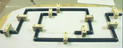
Once all of the pieces were cut and the ends deburred, I chamfered the joints a little for welding. This just means that you bevel the ends so that the weld takes place in a V-shaped groove for proper penetration. The components were then jigged to a board to ensure the proper geometry. It's not much fun trying to chase parts around on a table while trying to weld. And this way, the parts are going to be relatively accurate. The parts were tacked together, removed from the jig board, and then welded all around.
The pedals were made from the 2.5 x 4.0 x 1/8 6061-T6 angle that RR sends out with their aluminum kit. It is normally used for firewall reinforcement, but since my engine mount will bolt the four corners of the firewall adjacent to the longerons (rather than out in the middle of the cross braces), I don't need but about 10" of the 6' of angle.
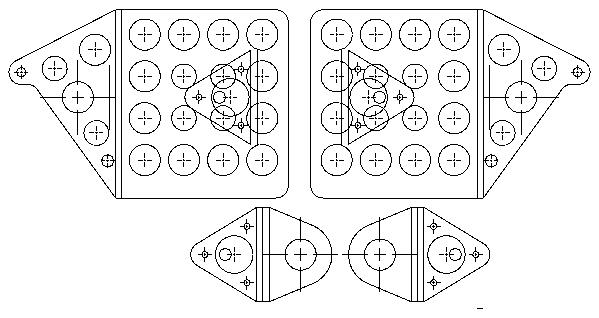
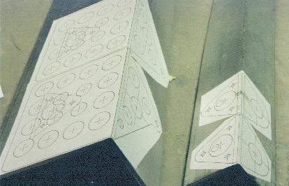
I drew up pedals on CAD, and integrated the pivot point for one side into the pedal itself (download rudped.pdf for a full size drawing). The plans version calls for bolting a piece of 3/4 channel to the pedal to act as a pivot. By integrating one half of the pivot into the pedal itself, I was able to replace the channel with an angle, while spreading the two pivot points 3 inches apart, rather than 3/4". Loading will be better, and should bind less than the stock arrangement. The pedals and brackets were cut out on my "wood cutting" band saw. The angle which serves as half of the pivot was bonded to the back of the pedal with some incredible stuff sold by Tra-Bond. Mark Lougheed sent me a sample, and it's tenacious stuff similar to JB Weld. Saved a few ounces on bolts and nuts here! The drawings above show lots of lightening holes, but I've yet to cut them out. That should help some more.
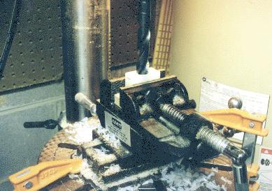
The nylon rudder blocks were made from 3/8" x 1" nylon bar available from Wicks. A drill press is required, along with a drill press vice. Clamp two pieces of materal in the vice (upper and lower halves) on edge, and drill a 5/8" hole on the dividing line of the two pieces. It helps to use a block of wood underneath the nylon so you don't drill a hole through your vice.
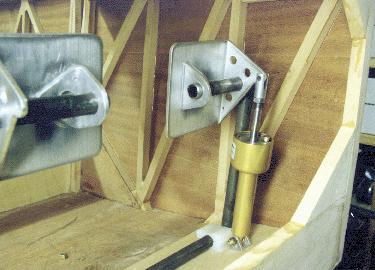
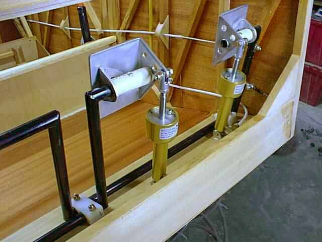
This picture shows the final result, except that a few bolts are missing. Note that my nylon bearing blocks are only 1" wide. This will provide plenty of bearing surface for this job. The blocks are fastened to the fuselage floor with AN3 bolts countersunk from the bottom of the fuselage. The brake cylinders are Matcos. They are mounted to the floor with a lightweight 3/4 x 3/4 x 1/8 6061-T6 channel and one bolt, rather than two angles and two bolts. Another few ounces saved!
The fuselage boat has extra spruce in the locations that the mounting blocks are located.
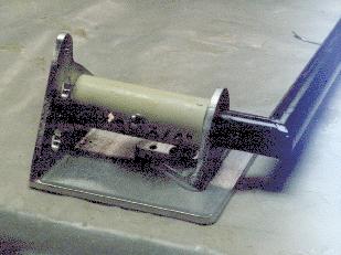
I didn't care much for the cotter pin and washer method of retaining the pedal to the cross bar (mostly because I kept breaking those tiny drill bits), so I cut a piece of CPVC pipe to do that job for me. It's held in place by a small #4 screw, and prevents movement of the pedal in either direction.
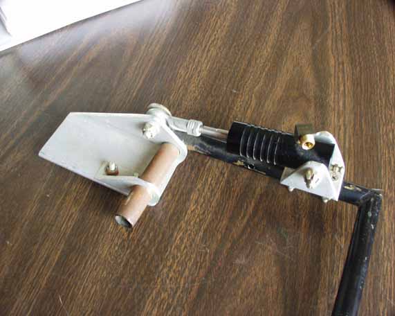
I saw this method at the Pine Bluff 2001 KR Gathering. The brake cylinder's pivot point is fastened to the brake pedal upright itself, rather than to the floor. This method solves a lot of funky geometry problems, I'd certainly consider it!
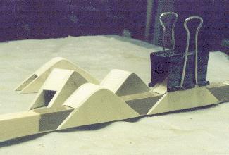
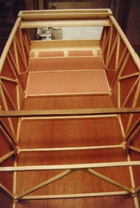
I made my rudder cable fairleads out of spruce and plywood scraps. The problem with these is that you can't get the cable out without cutting it. But I can't really think of why you'd need to remove the cable unless you were replacing it anyway. Still, I'd try a little harder to figure out a way to make them removable. This picture shows their construction, using packing tape and a spar piece of 5/8 spruce as a jig. I used Nylaflow tubing as a conduit through the passenger area.
Here's the final result. I'll have to confess that I never did go back and drill the lightening holes in them. Another weight-saving opportunity MISSED! Next airplane I'll do much better...
Return to Mark Langford's KR2S Project