Tailwheel update, March 2010 - My first tailwheel lasted me for about 1600 landings, including my "learning phase". At that point the tread was wearing a little thin, so I bought a new one from Aircraft Spruce. After installing the new one, it seemed noisier than the previous one during landing and taxiing. On a KR, the aft fuselage acts as a megaphone, and any tailwheel noise is amplified and aimed at the pilot. After about 200 more landings, it was noisy enough that I worried about failure, so I removed the wheel to see if the bearing was "toast".
Upon removal, I was amazed to see the balls were rusty, with no sign of grease. It actually rattled! since I still had my original tailwheel with the 1600 landings, I put it back on and things quieted back down again. I put another 400 landings on it, and now it was really getting thin, so I ordered a new one from Aircraft Spruce.
This time I had the good sense to check the bearings, and was shocked to see no sign of grease again! The thing literally rattled when shaken. This was about a year after I'd bought the previous one, so this is more than one that "slipped through the grease crack". Upon checking the Aircraft Spruce catalog, they sell the "4 inch Homebuilder's Special Tailwheel" for $23.85, and also mention a "Longlife Sealed Bearing" for $2.95 each, which makes you wonder what they ship in the "Homebuilder's Special" tailwheel. I called and asked if the special bearing was an option with the tailwheel, or if they were a separate item that was supposed to be user-installed. I was told the bearings are a separate item, and could not be bought installed. Hmmmm. I wonder why you'd want Longlife Bearings for your tailwheel, when the ones in my original tailwheel were still fine even though the tread is almost gone? I thought the Aircraft Spruce catalog might be a clue..."These high quality bearings are superior bearings furnished with homebuilders tailwheels" , but that doesn't even make sense, unless they left out the "to" in front of "bearings furnished".
I checked the original wheel that came on the tailwheel assembly and clearly it was grease packed, and appeared to be a much better "sealed" bearing, so somebody thought it was a good idea 10 years ago when I bought the original one from Wicks. Gee, has Aviation Products started shipping "short life" bearings with their swiveling tailwheel assemblies now? That deserved a phone call! I couldn't imagine that AS&S or Aviation Products would think that a shopping cart caster with a cheap bearing with no grease could stand the rigors of a 70 mph experimental aircraft landing, or would intentionally sell wheels with no grease packed in them for any reason. I'd think (and now I KNOW) the life expectancy of a dry bearing called upon for 65 mph touchdowns is going to be "somewhat" limited!
So I called Aviation Products and asked what kind of bearing they put in their tailwheels and was told "heavy duty sealed bearings, greased for life is the only way we sell them...why wouldn't you use the best?" I also learned that Aircraft Spruce orders the assembly from Aviation Products MINUS the wheel for some reason! Although I didn't hear it from Aviation Products, one must assume that AS&S substitutes the less expensive R&K caster with the ungreased and unprotected bearings and saves a few bucks. And after your ungreased bearings rapidly wear out, you'll either buy a new tailwheel (with no grease), or if you're really enterprising, you'll put new bearings in it.
But maybe they figure us airplane builders are astute enough to notice (although I didn't) that there's no grease down in those bearings. So maybe I just need to get smart and grease the things...but how? I guess I could rig up a syringe with a tube fastened to it and sort of dab some on the outside of the bearing, but that's not how I learned to pack bearings. In the automotive world you use a "bearing packer", but the 5/8" hole for the shaft won't work with that. I've seen pointy attachments for grease guns, but it wouldn't fit down the hole. Or you just work the grease in by hand...if you have them in your hand. So I called R&K bearings to ask how you're supposed to lube these dry bearings down inside that tiny hole and was told that those are sold for use with "hollow shafts with grease fittings". Hmmmm...the Aviation Products wheel shafts don't have grease fittings in them, and have no accomodation for a grease fitting, so how's that supposed to work? I guess that's another reason Aviation Products only provides sealed, greased bearings.
But how do you put new bearings in this thing? As a former mechanic, I thought this would be a piece of cake to upgrade my old rusty balls to a sealed setup...after all, I have a 30 ton press in my basement. The 30 ton press woudn't touch it when trying to press the shaft spacer through because I was basically trying to press the bearing apart. Then I realized you'd need a special tool that could reach down inside and past one bearing and expand to drive the opposite side out. R&K casters agreed...it was a special tool.
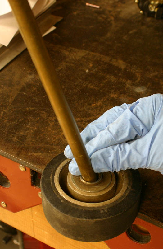
After a beer or two, it occured to me to try a smaller diameter brass drift inserted at an angle from one side, and whack on the other side. It took about 10 whacks, with a 180 degree rotation each time, for the bearing to fall out. Of course if these were new bearings this process would damage them by overloading one or two balls rather than all of them sharing the load, but it can be done. You wouldn't want to do this unless the bearings were bad, so driving out the ungreased bearings for a proper grease packing is probably a non-starter...you'd just have to trash them and install the lubed ones. And when you're done you could have just bought the sealed version from Aviation Products and saved yourself the trouble (and the premature bearing failure).
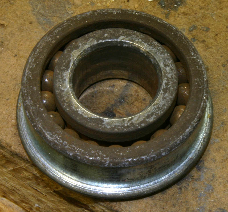
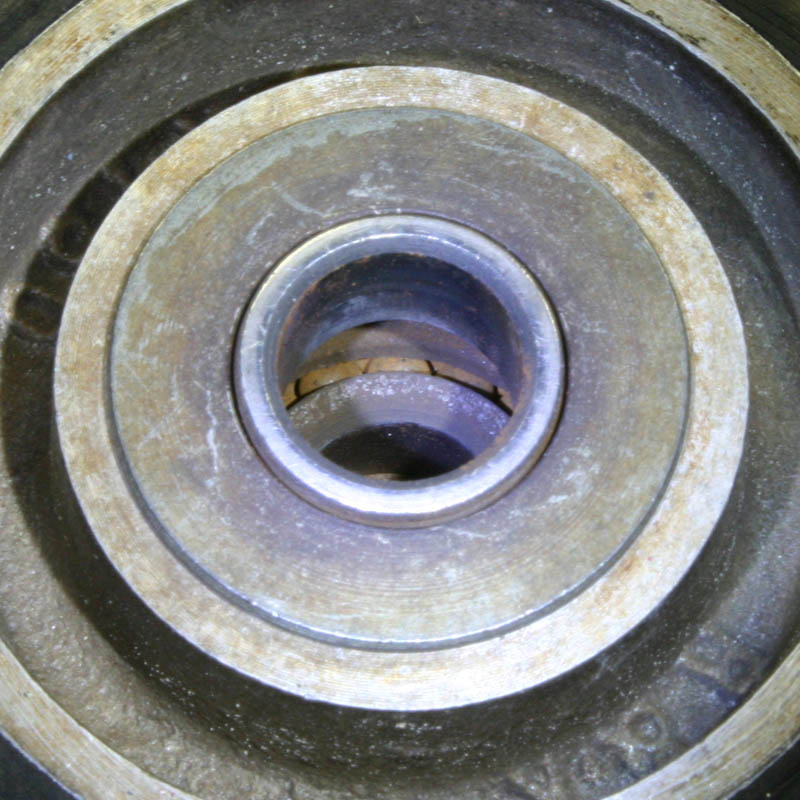
Here's a good view of the rusty balls. Not what you want on an airplane that lands at 65 mph, or even 40 mph, or even your shopping cart, unless you have hollow axles and grease them (as intended by the manufacturer).
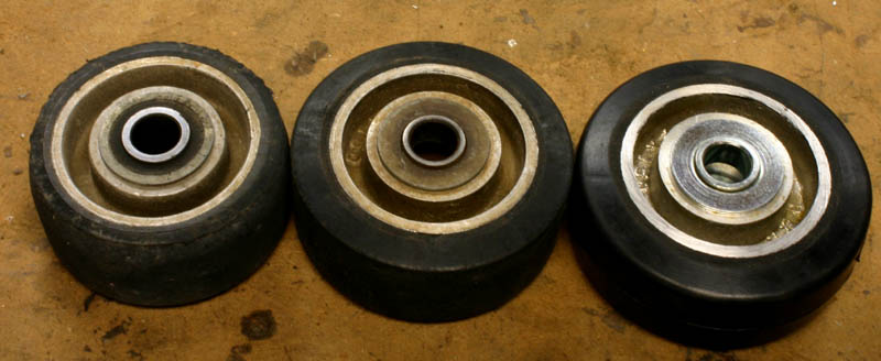
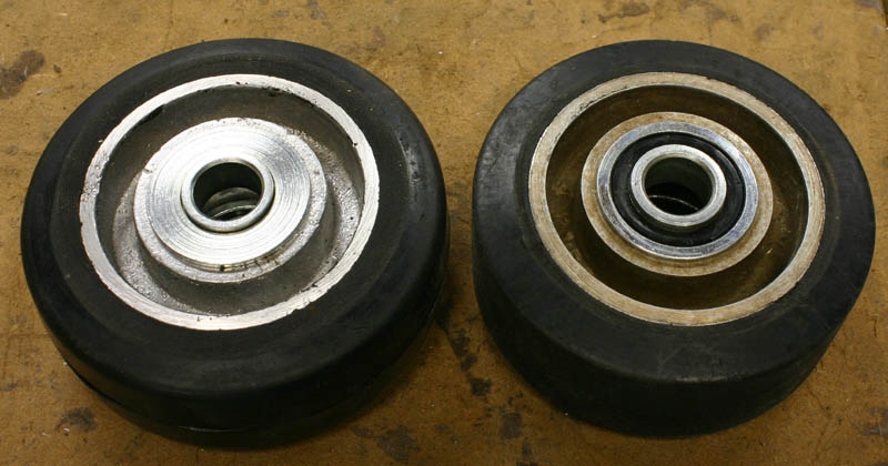
The original, the rusty one from AS&S (Aircraft Spruce and Specialty), and the soon-to-be-rusty "new" one. As you can see, the original provided a lot more service than the un-lubricated version from AS&S, even though the casters are both the same model from R&K, which can be ordered with your choice of several bearing configurations. AS&S chooses to send you the only unsealed version (and presumably), whereas Aviation Products chose the sealed version that outlasts the tread. we're only talking a few dollars difference between sealed and unsealed, so I don't get it. I called Aircraft Spruce to notify them that they were selling tailwheels for aircraft that had no grease in their bearings, and the customer service person I talked to seemed concerned, and would speak to her buyers about it. The next day she called back and said something like "the buyer says these are the proper bearings, they are what we specify, they are what they are, and we have the optional Longlife Sealed Ball Bearings, p/n 06-00060 if you want to upgrade". I wondered how long this had been going on, and my 2005 catalog shows the same "longlife" replacement bearings. That's a long history of replacing un-lubed bearings.
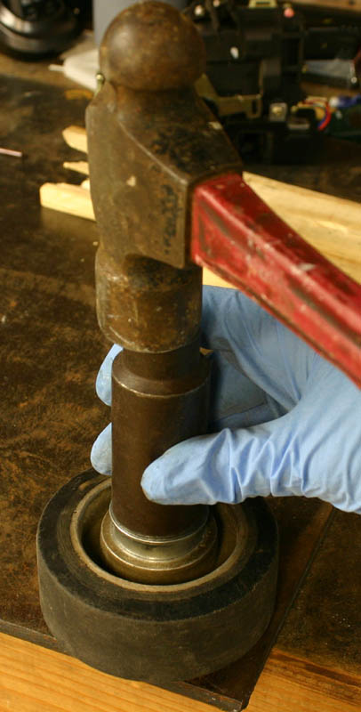
Well the last thing I wanted was to buy bearings from Aircraft Spruce to fix a problem that they apparently created, so I bought a set from McMaster Carr and quickly installed them using a large socket (the press would have taken another minute or two, but would have been the "proper way" to do it). I flew it a few hours later and it was so quiet I forgot to listen for it.
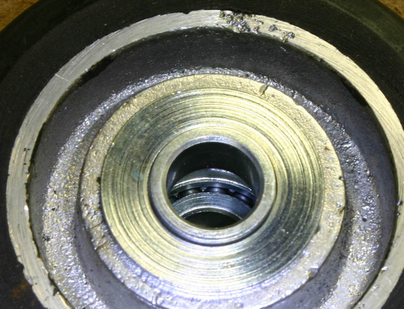
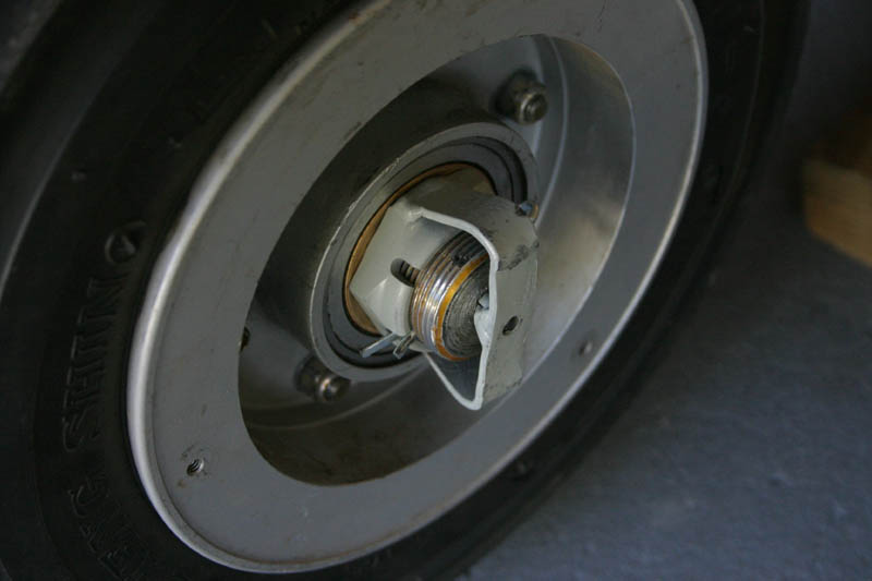
The sealed bearing in my second tailwheel looks like proper aircraft equipment, unlike the dry bearing version on the left from AS&S. And just so you'll know, Aviation Products sells their full swiveling steerable tailwheel assembly to the public for $238, with sealed and lubricated bearings installed in the wheel. Or you can buy what appears to be the same unit from Aircraft Spruce as the Homebuilder's Special 4" Diameter Full Swivel/Steerable, P/N L-692, $288.95 (a mere $50 more), and get bearings that rattle and are not lubricated in any way. Wicks appears to sell similar dry bearings on their tailwheel, judging by the photos on their web site, but I could be wrong about that. They show a 3/8" bore tailwheel in the picture. Their 4" tailwheel info is confusing, as is most of their website. For example, I'd think they'd still sell the 4" swiveling/locking tailwheel assembly, but you'd never know it from their website.
Contact info for Aviation Products:
Aviation Products, Inc:
114 Bryant St.
Ojai, CA 93023
ph/fax (805) 646-6042
Aviation Products also sells all replacement parts for the assembly, such as the aluminum housing itself. I believe their wheel is $39, with "good" bearings...
Gear Leg Extension Experiment - August 2007
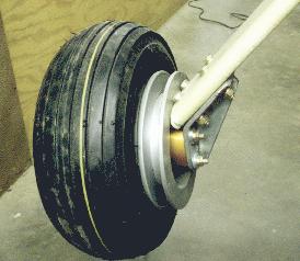
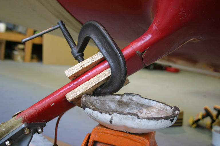
I finally got around to extending my gear legs. What I expect from this is a lower landing speed due to the higher angle of attack (getting closer to full stall and 4 more inches of prop clearance so I can spin a longer, more efficient prop. Now I can move from a 54" diameter prop to a 58" diameter prop, and still have an extra 2" of ground clearance.
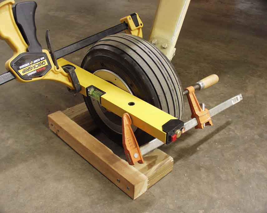
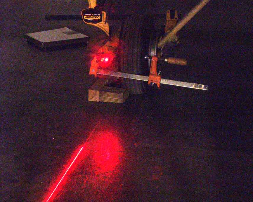
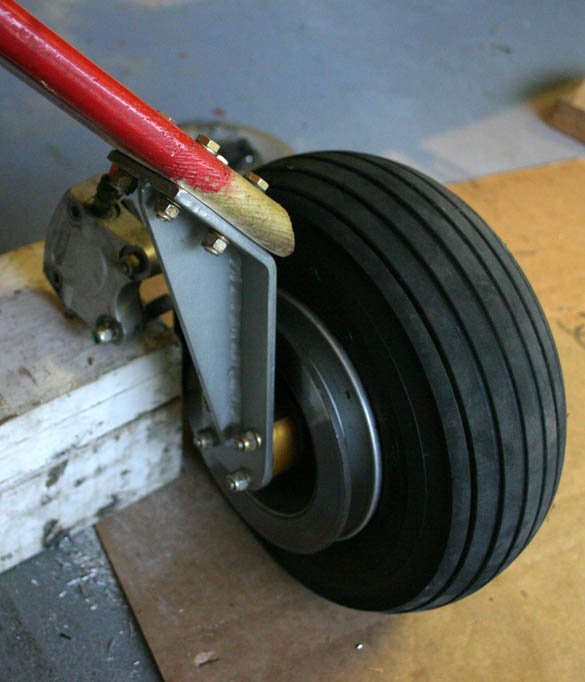
There's 3.75" of vertical lift here, which is equivalent to gear legs being 5.3" longer (almost as long as Larry Flesner's and Jeff Scott's gear legs). I also slid the wheels back a tad to see if that'll improve three point landings. The caliper is awaiting hookup in this picture. The extensions are made of 1/4" 4130 steel, TIG welded, and powder coated, hacked out in my basement (and it shows). These come with a 12 ounce weight penalty each, but I could've (and should've) shaved some of that off.
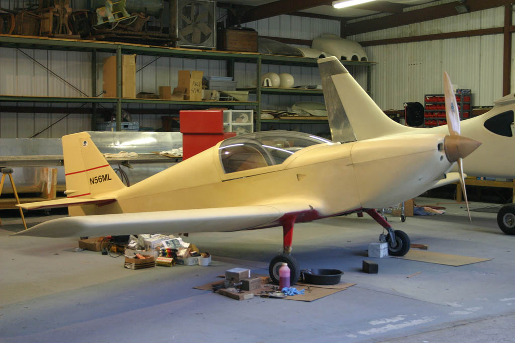
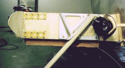
As you can see here, N56ML got a lot more "proud", and looks kinda "bad" to me! Taxi visibility will get worse, but that's OK, because it just means I'll have to sit up on the seat a little higher. It does resemble Larry's and Jeff's airplanes. Now wheel pants and gear leg fairings can commence.
Well, the longer gear didn't last long...the legs were too floppy, given the longer moment arm they were working through, and landings were a little on the squirrely side as the were able to twist around more. Taxiing visibility went from dismal to non-existant, and it was a lot harder to step into the plane. I couldn't detect any real change in landing speed either. So they only lasted about two weeks before I removed the extensions and got back to normal. To be fair, I could have made them work by wrapping a few more layers of glass around the gear to stiffen them up, but the over-the-nose visibility would have been more dangerous.
Wheel Fairings - I added wheel fairings in September 2007, because I didn't want to show up at the KR Gathering again without them. It didn't take nearly as long as I thought it would to attach them...I just needed to sit down a study the situation long enough, and then just DO IT. I bought Klaus Savier's Lightspeed Engineering wheel pants for an RV, which are not cheap, but are reputed to be some of the most efficient. RV wheel pants are similar and less expensive. They came as a matched set with joggles already done, splitting vertically around the axle point.
I'd have used John Backer's, except with the big Cleveland brakes, I'd have had to cut a huge chunk of those beautiful pants off and fair the whole mess in around the lower brackets, and John's fairings are way too nice to butcher like that.
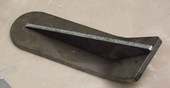
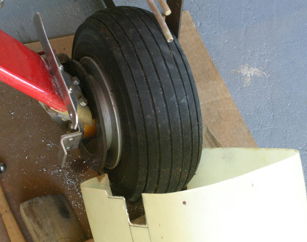
The first step after leveling the fuselage (so the fairings are level with the world) was to set the rear wheel fairing on a block of wood and ascertain where to remove fiberglass to enable it to slide forward for a tight fit. Then I bent up an aluminum bracket to put under the two upper bracket attach bolts, which picked up a screw on both front and back parts of the fairing.
Then I used two pieces of angle screwed together to form a Z-bracket, fastened under the rear two lower bracket bolts, which take care of the lower rear part of the fairing.
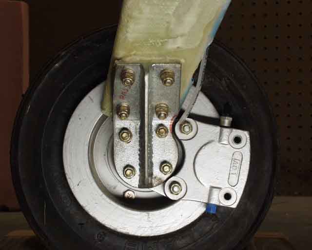
The axle was about the only outboard place I could use for support, so I welded a bracket onto the axle nut, and then welded a nut plate to the center of it (centered so it wouldn't matter which cotter pin hole was used).
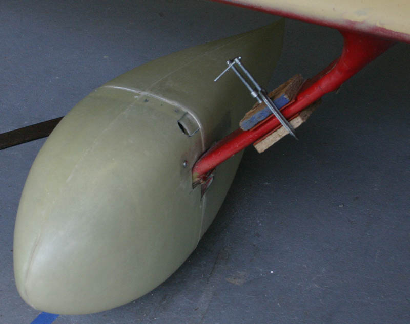
After the aft fairing was mounted by slotting it to slide onto the gear leg and clear the tire, I did the same with the front. Because the fairings are translucent, I could see where to match drill the axle screw hole and that leveled up the fairing left to right. Then I blocked up the front and rear of the fairing so it looked level, and parallel to the top longeron. Then I just match drilled the fairing and the aluminum brackets, then came back and installed nutplates on the alumium parts, and screws through the fairings and into the brackets. The last step was to match drill the mating halves about every four inches around the periphery of the joggle to connect the two halves together...nutplates on the inside, then screws through both parts into the nutplates.
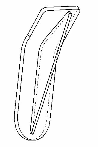
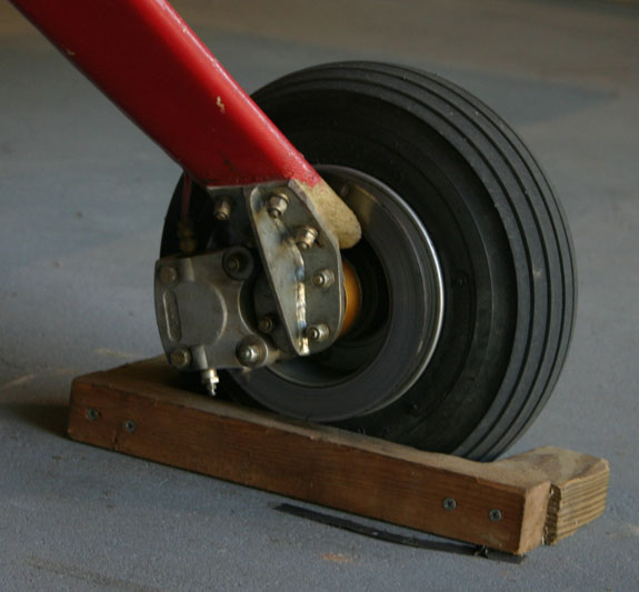
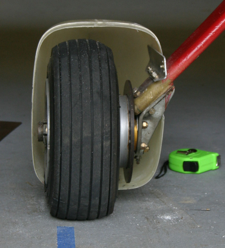
The extra leg notch in the forward part of the fairing near the top was done when I had the previously mentioned gear leg extensions installed, and was toying with adding fairings at that point. That upper location would be optimal because it would eliminate the sharp angle between the leg and the fairing, improving the drag situation, but it was not to be. The OSB clamped to the gear is to facilitate jacking the plane up with a common floor jack. It's funny to see silicone sheet in contact with the leg itself. I used to be so careful about such things...
The whole process was much quicker than I thought, and took less than a Saturday, as I recall. They proved to be worth a solid 10-12 mph on the top end, so I'm still kicking myself that I didn't install them earlier, given how easy it is...
Next airplane I'll use something like these wheels with brake disks that are recessed. This would allow a smaller and narrower wheel fairing like the very aerodynamic ones John Backer makes. These wheels are also lighter, I suspect, because the disks are lighter.
Another tailwheel update, March 2020 - I've been flying this same "Homebuilder's Special" tailwheel for about 1800 hours. This doesn't sound like many hours, but keep in mind that I have logged about 5000 landings during this time, due to my incessant habit of endless touch and go practice. The same tailwheel has been flying on my KR2, N891JF, until I retire and have time to get N56ML back in the air again. And either my landing skills are degrading, or the plane is getting even more squirrelly when landing, so I figure a new tailwheel assembly is a quick step at troubleshooting the problem. Besides, I'll need another tailwheel assembly for the N56ML resurrection!
So I ordered a new tailwheel, but this time, direct from the manufacturer, Aviation Products (address is above). The photo on their website looked like mine, so I ordered the 20 degree version designed for 1.5" to 1.75" tail springs. But when I received it, it looked completely different....it was missing the pocket on top for tail spring mounting, and the hole was over a half inch forward of my current one. I called Aviation Products and verified that it's the only model they sell (nothing similar), and that's the way they were always made. This makes me wonder if Aircraft Spruce (where I bought my first one) does this extra machining to make the assembly more versatile (can mount either above or below the spring), and lighter.
Return to the KR2S Construction.
Email me at ML "at" N56ML.com