Mark Langford's KR2S Project Page
Fuselage Construction
originally created Dec 31, 1994... updated May 2009
I started on my fuselage in May of 1994, and finished it by the end of the year, taking a total of about 60 hours, according to my building log. The pictures below are a smallish and not the best quality, because they were taken with a film camera and scanned in.
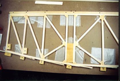
The fuselage sides are constructed from 5/8" square spruce. In this view, the upper longeron is on top, and the lower longeron is on the bottom. The firewall wall end is on the left. The upper longeron is defined (in the plans) by a straight line, which I ensured by screwing a straight board down to the table as a guide. As you can see in the photo, I used square blocks placed about an eighth inch away from the lower longeron and screwed to the table with one screw (so it's free to rotate). I then used builder's shims to tighten up the joint by lightly tapping the shim between the block and the lower longeron. Not too tight, because you don't want to force all of the glue out of the joint. Although the plans call for using wax paper beneath the joints, I used 4 mil "builder's plastic" instead. Wax paper leaves a wax residue that will impede future epoxy joints' adhesion. Note the pine spacer (which I probably should have wrapped with duct tape as an epoxy release) that maintains the opening that the main spar will eventually go through.
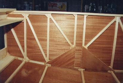
"Do I have to go to the trouble of making all of those tiny gussets, when it would be much easier to just cut out little plywood gussets and glue them in place?" you ask. You can build your plane however you see fit. But you should be advised
that Tony Bengelis (among others) says that plywood gussets are better than
none at all, but solid Spruce gussets are the best.
If "gusseting" is all you're after, plywood may work almost as well as spruce, but one of the major
purposes of spruce gusset blocks in the KR fuselage design is to increase the area of the glue joint between
end grain members (verticals) and longerons. If you've ever tried to break a
joint without the gussets, it's really easy. With spruce gussets you have
three times more area to make that connection, subtantially more than a
plywood gusset gives you, and now two of the joints are parallel to the grain, a much stronger joint (stronger than the wood itself)than the end grain joint you'd get without the spruce gusset.

Speaking of gussetts, Dayton, Ohio KR builder Ron Willett shows us one of many gusset clamps that he used to apply light pressure to his gussets during fuselage construction. The plunger is just a nail, and the spring is from the local spring supply house.
These gussets, and anything else you glue together with T-88, need only light pressure to make a good connection. Too much pressure will squeeze all of the glue out leaving a weaker joint. I always brush epoxy onto both surfaces and let it soak in for 5 minutes or so, then apply a little more and join the two pieces.
After a truss (fuselage side) is constructed, and it's time to skin it with plywood, glue
the plywood to the side that was facing DOWN. When you miter your
verticals and gussets you try your best to make the joints perfect on the
side you can see, but what happens to the side facing the table that you
can't see? Since you can't see it while you're fitting and gluing, the
joints won't be as tight on the down side, so cover THAT side with skin to
both strengthen it and hide it. I didn't have the good sense to do this,
so the joints that you see inside my boat are the joints on the worst
looking side.
And one more thing...when you epoxy the skin to the fuselage sidewall frame, trace around the frame lightly with a pencil on BOTH sides of the plywood, and then remove the frame and brush a thin layer of epoxy onto both the plywood's inside surface and the mating side of the spruce frame. Mate the frame to the plywood, and put a small (#4) countersunk wood screw through the plywood into the frame at two of the corners to keep them in aligment (this is easy if you hang the corners over the edge and screw up into the frame). If you don't put these screws in there, or find some other way to "pin" the plywood, it will very likely slide out of alignment before the epoxy cures. Then flip the whole works over and staple the plywood skin using your previously outlined pencil marked out side as a guide, with each staple straddling a continous nylon cord or fine wire (safety wire works well) that can be used to pull one leg of the staple out to aid in staple removal later. When all the staples are in, remove those two little screws (if you use T-88, they'd probably be there forever if you let it cure with them in there) and flip the whole thing back over so the plywood skin is on the work bench, spruce on top. This way the excess epoxy will run down onto the inside of the skin, leaving a nice little fillet in the joint between skin and spruce members when it's all cured. This also gives you the opportunity to wipe away any drips or serious excess epoxy. When removing the staples, first pull the wire/string out to liberate one leg of the staple, and then use a wide-nosed pair of pliers as a fulcrum against the plywood to roll the staple out of the wood.
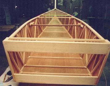
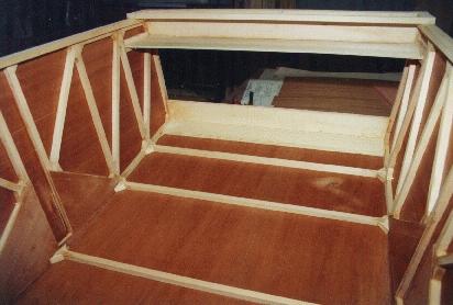
The "boat" is formed by standing the two sides up and stretching them around blocks screwed to the table. I used a full size plot on the table to make sure the sides were symmetrical, and a plumb bob with the centerline to deal with the top. This was certainly overkill and not required. This is really not rocket science, although I sure tried to make it that way! Others have been constructed using several trapezoidal jig frames which define both top and bottom dimensions. I'm sure that works too, and guarantees a square fuselage (not that it matters much).
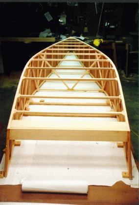
Completed boat with vertical stabilizer spar and firewall supports installed. A wide angle lense and goofy perpective make it appear warped and twisted, but I assure you, this is one symmetrical fuselage.
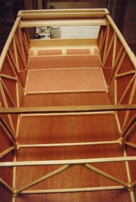
View showing urethane foam installed under cockpit floor for noise insulation. Also shown are hardpoints for rudder pedal installation.
Firewall details.
Spar gusset details.
Update: December 2000
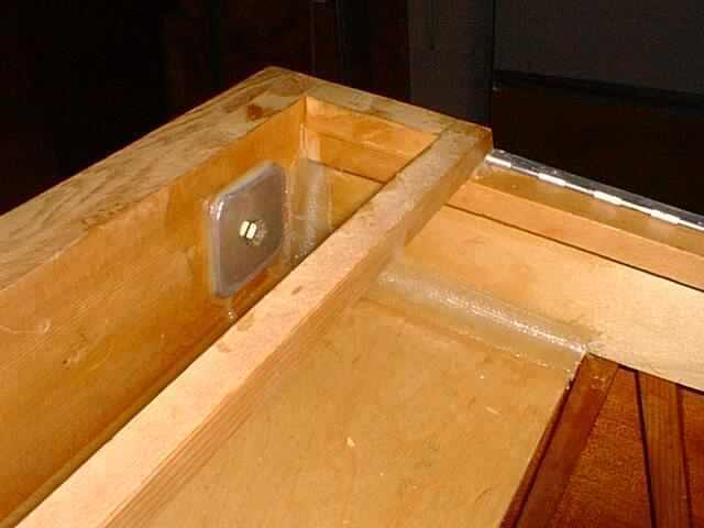
Here's what I did to reinforce the connection between the firewall shelf and the fuselage sides. 3 layers of 1" wide 9 ounce fiberglass tape applied over a fillet of flox will do that job in my application. The aluminum backing plates that accept the engine mount bolts are 2" from the longerons, and measure 2"x2"x.188". Since my mount doesn't connect in the middle of the firewall (like the plans call for) I don't need those two 44 ounce aluminum angles fastened to the firewall and shelves. The plans call for these to spread the loads from the center mounted engine mount out to the longerons. My engine mount goes almost right to the longerons, so I'll save that 5.5 pounds, and use the aluminum for something else!
What would I do differently given the opportunity? I'd probably use all of the 14 feet of longeron material that Wicks Aircraft sent me, by adding 2.75" to each of the seven bays AFT of the aft spars, yielding a plane 19.25" longer. Another option is to add another bay back there, with the same dimensions as the others. Either way would probably be just about right to improve stability using the stock width horizontal stabilizer. The method you choose to do this may require a little thought regarding the length of the plywood that you'll be adding to the sides, since the scarf joints need to occur over a vertical member.
Return to Mark Langford's KR2S Project