KR2S Construction Page
KR2S Controls
updated May 26, 2003 (Originally written Nov 11, 96)
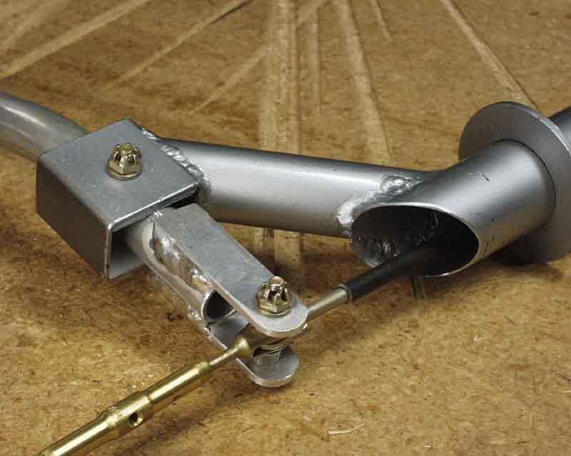
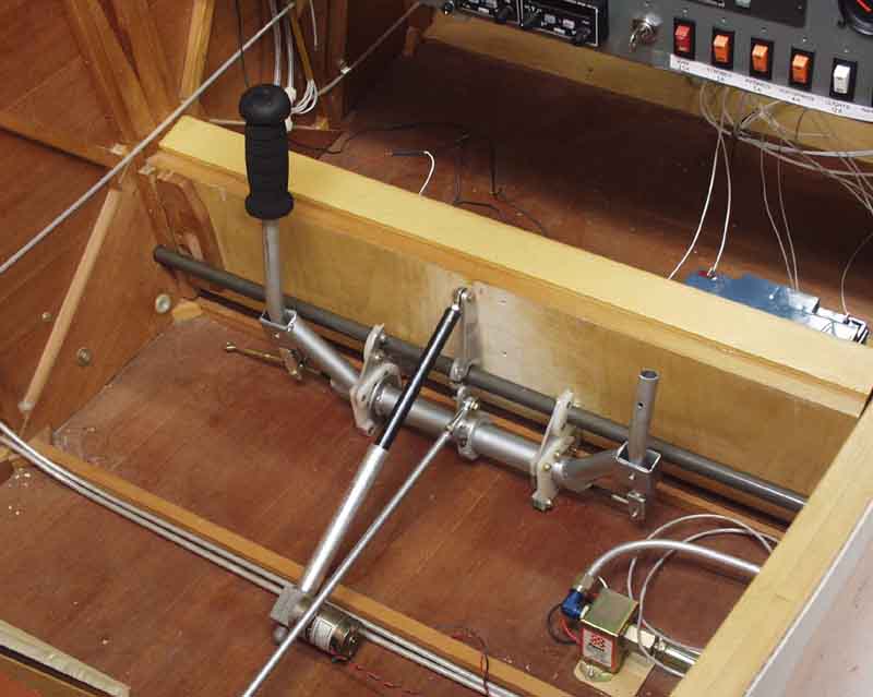
I decided to use a hybrid cable/pushtube systems for several reasons. The plans version stick leaves the elevator cables ABOVE the sling seat (usually). This enables passengers to accidently step on the cable, with the potential for exceeding the strength of the bellcrank or stretching the cable. Some folks build an "armrest" to cover the cable, but that cuts into the already small seating area. I thought it would be much nicer if a pushrod were used to connect the stick to a bellcrank on the aft spar, completely below the seat.
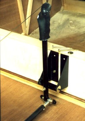
This center stick is built per plans, but the bottom is connected to a .75" .028" diameter 4130 push-pull tube. Because I have only one degree of wing incidence, I have a 1.75 inch gap between the bottom of the aft spar and the nearest 5/8" spruce cross member. This gives me plenty of room for the tube.
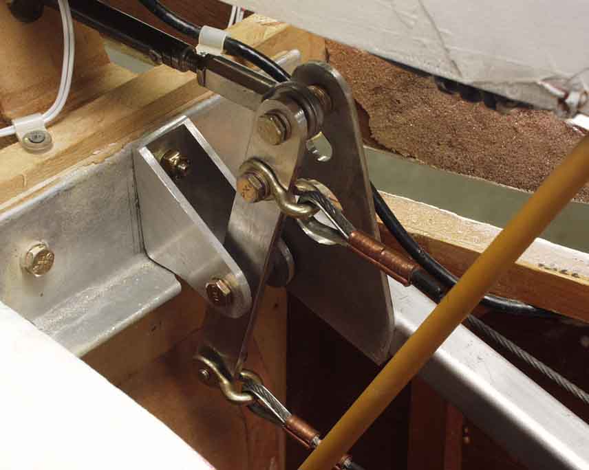
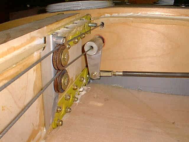
The standard cable pullies are replaced by a bellcrank. Control stops can be provided here, rather than at the elevator bellcrank, to limit travel. This eliminates a lot of stress on the rest of the system when limits are reached.
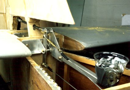
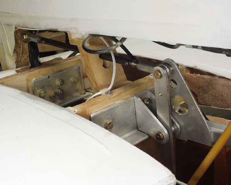
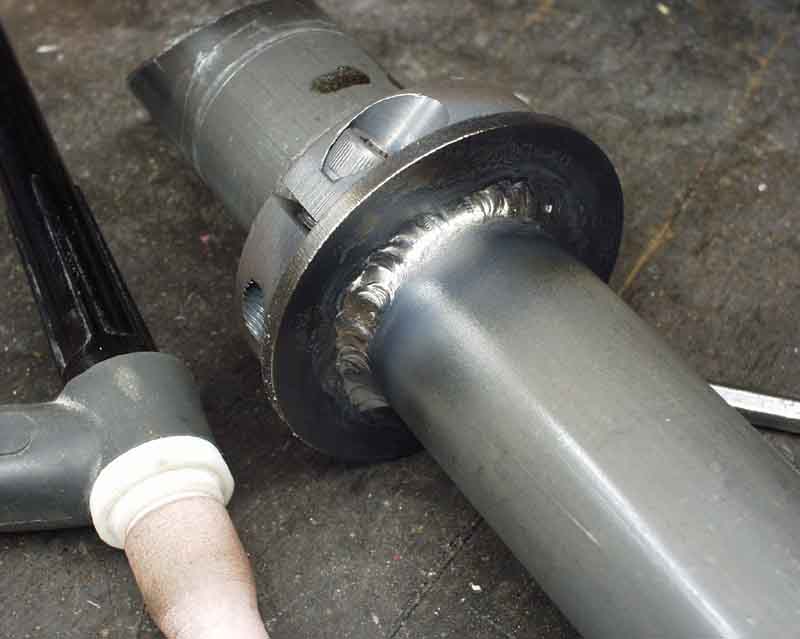
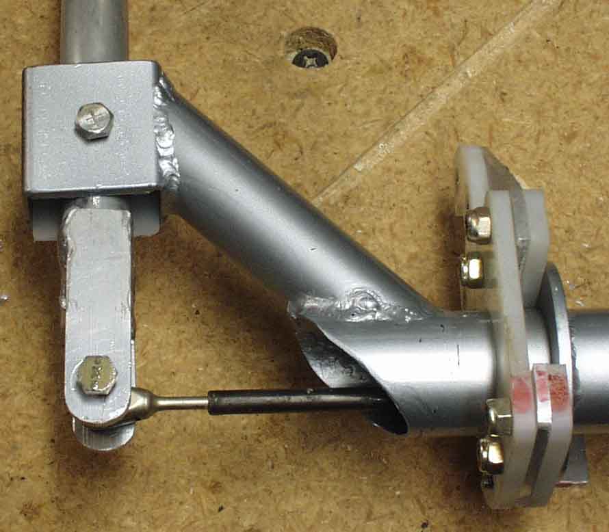
At the elevator the cable is returned to a pushrod which passes through the center of the vertical stabilizer front spar. What this setup buys me is a simple way to mount an internal elevator counterweight. The long 3/4" aluminum tube will have a 20 ounce lead weight on the end, rather then the cup full of washers. Rebalancing becomes simple in the event of an elevator paint job. This internal balance works great, and eliminates the requirement for aerodynamic balances on the tips of the elevators.
Having said all of this, you can't beat the stock cable system for light weight. That's why I used cable on the long run from aft spar to horizontal stabilizer: it's much lighter than the large pushtube (or two tubes and idler) that it would have to replace. But the big advantage of my system is the simplicity of the internal elevator counterbalance.
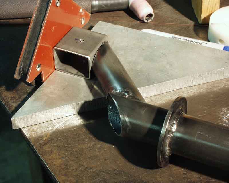
Also shown in the photo is the adjustable horizontal stabilizer setup which allows me to tailor the horizontal stabilizer incidence. Because I'm using an airfoil that's never been flown before (hey, that's why they call it EXPERIMENTAL!) at a different incidence, with different horizontal stabilizer airfoils, the horizontal stab incidence is hard to nail down. Particularly with the effects of cowling, propwash, canopy, and fuselage aerodynamics. So I've calculated the horizontal stab angle as best I can, and have built it to be adjustable. My plan is to fly it with half fuel and no passenger, trimming to level flight. I'll land without disturbing the trim tab from it's "cruise setting", and adjust the horizontal stab incidence to compensate. By iterating on this process, I'll eventually nail the horizontal stab incidence such that it will not produce any more drag than required for proper stability at cruise. When I find out what it is, I'll be able to reverse engineer the aerodynamic effects of the cowling, propwash, canopy and fuselage contribution. And I'll let everybody know what I've learned about their effects, and what could stand a little tweaking.
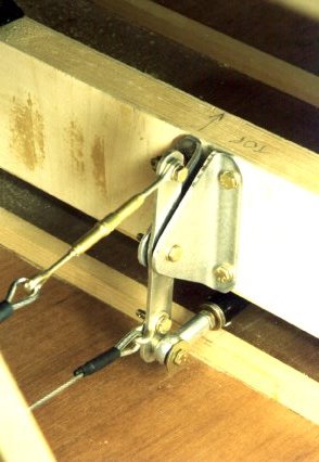
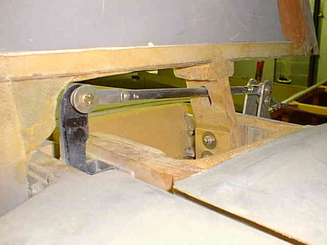
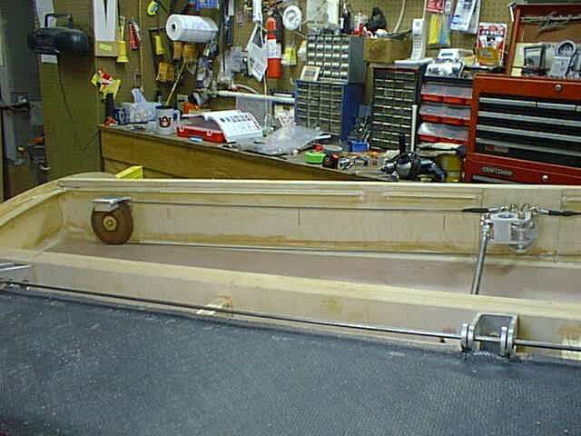
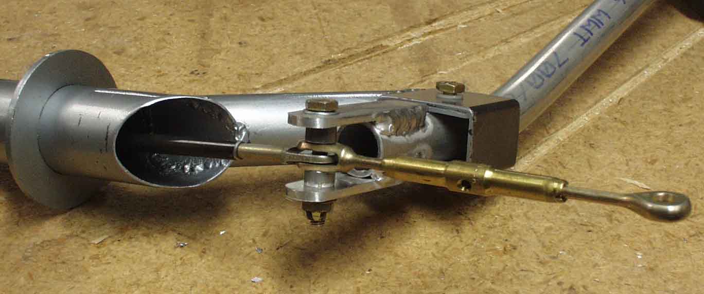
Another view of my adjustable horizontal stabilizer, along with the elevator counterbalance. If you're wondering how it's adjustable, right now it's not. The spar is clamped between two angles on each side. If adjustment is required, I'll remove the two bolts on the front side, insert a drill thru the two angles (with sandwiched spar) and slot the spar. My spar is 3" tall, so I can afford a slight elongation. 1/10" will get me .75 degrees of incidence change.
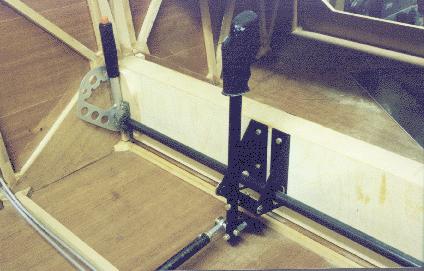
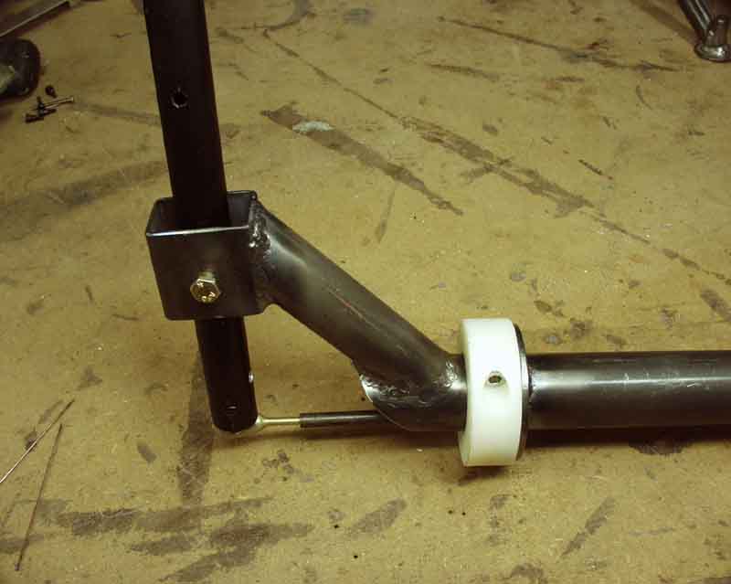
Control stick mounted to aft face of main spar. Note flap handle to pilot's left (that would be ME!). Flap torque tube runs through stick mount lightening hole, avoiding aileron cables. The problem with this center stick setup (and for all KRs built per plans) is that the stick pivot is about 3" above the aileron cable. What this does is stretch the aileron cable whenever the elevator is operated! Not good at all, in my humble opinion. The "solution" I've seen employed on some KRs is to hack out a huge slot in the fuselage wall to allow that travel, and not providing any fairleads between the two aileron bellcranks (left and right, mounted to the wing attach fittings). This minimizes the stretching, but is still nowhere near optimal. What you really need is to pivot the stick about the axis of the aileron cable, eliminating ANY deflection of the aileron cable during elevator operation. That's what I eventually did (see below).
Flap torque tube bearing is nothing more than 5 ply birch plywood. If I ever need a bearing here, it will already have a mounting face. I'll sand most of the excess plywood away before finishing the wings off in order to save weight.
Update - as of May 25, 2003
With the single stick design "detailed" in the plans, the pivot point for the elevator action is about 3" ABOVE the aileron cable axis, so you have to deflect the aileron cable itself to make the elevator work, and vice-versa. The tighter the aileron cable, the more the elevator wants to stay in one certain place, which is wherever the stick ends up when the aileron cable is straight through the cockpit. Now if your elevator doesn't happen to be at the optimal position for cruise at this point, you're going to have to trim it out to maintain altitude. That's where the drag comes from. The aileron cable acts as a "centering spring" to keep the elevator in that certain place. The elevator wants to be wherever the stick is "biased" to, whether or not it's optimal for your cruise condition. If you were careful enough and liked to experiment, you could find the sweet spot where the elevator trim was neutral, and the aileron cable was undeflected through the cockpit (at one speed and load condition, anyway).
I couldn't stand the thought of senselessly stretching the aileron cable every time the elevator was moved from its neutral position, so I decided to redesign the stick. At the same time, it became obvious that with only a tad more material, I could make it a dual stick setup, and give myself and my passenger (or student) an little extra leg room, AND I'd be able to fly with either hand. So I set about designing a new dual stick setup.
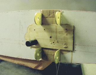
Recall that my aileron cable circuit is confined to one plane, the aft face of the main spar. This photo was taken just before I closed out the bottom of the outer wing, and shows the aileron "return" cable going through a nylon fairlead that's inserted into the end of the flap acutuation torque tube.
Here you can see the rest of the path that the aileron cable takes in my plane, with the aileron bellcrank assembly located on the main spar, rather than the aft spar. A pulley located near the end of the main spar returns the cable.
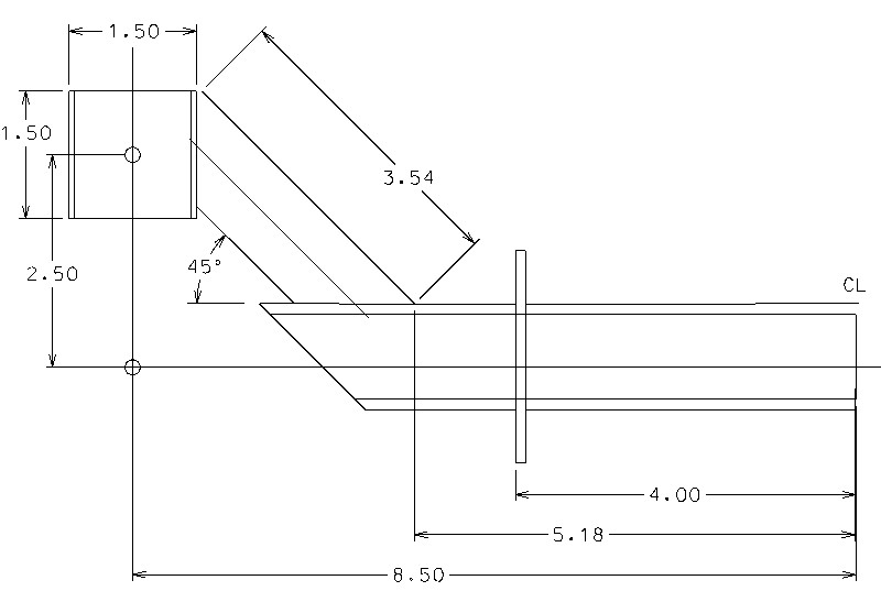
I looked at several other stick designs, and copied the good stuff, and improved where I could. Given my new-found ability to weld either 4130 or aluminum, this was something that was now feasible, rather than wishful thinking. Looking through the Wicks catalog, I chose the thinnest, smallest 4130 sections that I thought I could weld that would still be strong enough. I ended up with 1.25" x .035" OD tubing for the main body, with 1" tubing extending up at 45 degree angles to a 1.0 x 1.5" x .065" wall rectangular section 1.5" tall for the part that the stick pivots in. The big washers on the main tube are part number 91083A039 from McMaster Carr.
Now that it's built, I realize that I could have easily gotten away with 1.0" diameter for the main body, and .75" for the diagonals, since the vertical travel of the shuttle rod is minimal, and it would be plenty strong enough. And going to 1" would have allowed me to drop down to .028" wall, rather than .035 wall, saving even more weight. It was really no problem welding the .035 wall 4130, and .028 is just about as easy. I'm using a Lincoln Square Wave 175 Pro welder, and I can't imagine how it could get any easier. I tried gas welding 4130, and stick welding, and I'm a complete failure at both!
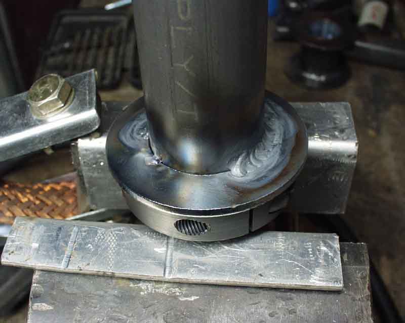
I used a 1.25" steel "clamp collar" as a fixture to weld the two steel washers (from www.mcmaster.com), so they would be perpendicular to the shaft. These act as centering locators, and slide against nylon rub blocks.
Not too bad for a bozo, huh? The guys at the shop said they'd hire me as a welder if I ever got laid off!
Here's the "fixture" for welding up the rectangular section 4130.
Here's an early fit-up test, back when I was planning on using nylon clamp collars for bearings. The problem is that the nylon is an interference fit, and has to be honed out if you want it to slide, which is much easier said than done! So I went to 3/16" thick nylon, also bought from McMaster Carr (and I think Wicks sells it too). The shuttle tube is just a piece of quarter inch 4130 steel tubing that I tapped out for 10-32 threads and screwed an AN428 "hinge fitting" into it (an AN161 fork end is shown, which is fine too).
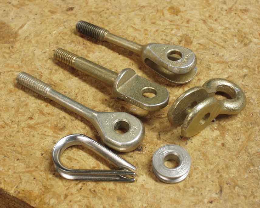
These are three of the choices that I considered as end pieces. The one I chose is the AN428 (second from the top). Also shown at top is an AN161 fork end, among others.
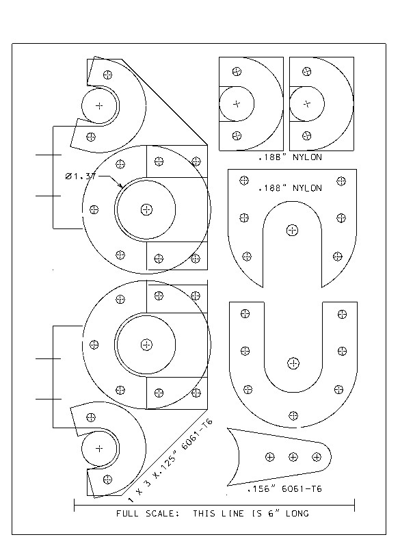
I created a pdf template file of the brackets and glued the templates to a leftover piece of 2.5 x 4 x .125 6061-T6 that was supposed to be used as the firewall reinforcing on the KR2S, and proceded to cut them out to shape. The other shapes are the nylon rubbing blocks and the elevator lever that is welded to an aluminum clamp block and clamped to the center of the stick after everything else is finished.
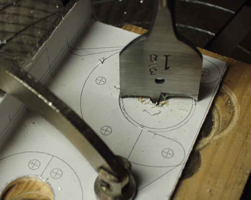
I used my "poor man's Bridgeport" to make the holes. These spade bits are wonderful when mounted in a drill press, and kept oiled while "milling".
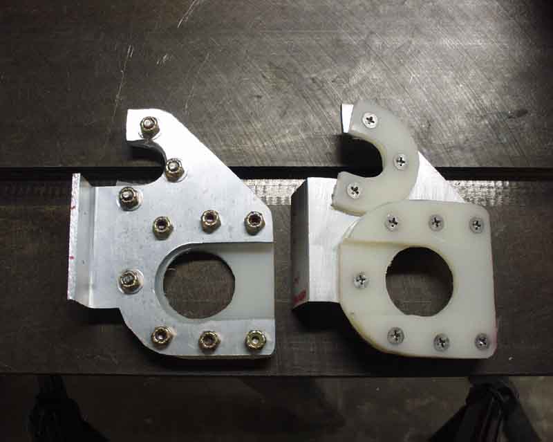
Here are the brackets and nylon rubbing blocks. Actually, these are number 7 and 8. Unlike my usual habit of making three attempts before getting it right, this time it took FOUR! The nylon rubbing blocks are held in place with #8 countersunk screws and nuts. The screws are Loctited in place in the tapped aluminum.
The upper cutouts are bearing blocks for my flap torque tube. Now that I've ditched the RR flap handle in favor of an RV electric flap motor, I wish I'd mounted this thing to the aft side of the aft spar instead of to the front spar. Then I'd have the aileron return cable exposed, and I could easily have put a turnbuckle on it for adjustment to help center the ailerons. As it is now, I'll have to add an access plate under one of the wings to get to it, which will not be good for drag.
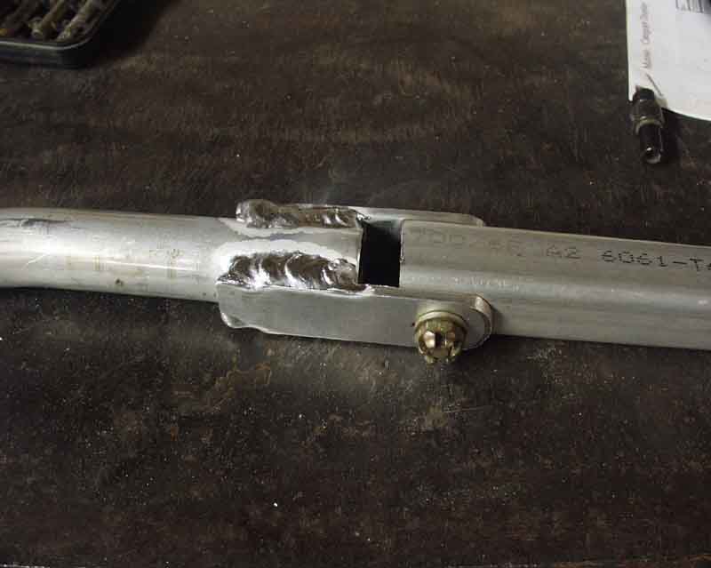
Control sticks are .75" x .035 wall 6061-T6 tubing with 1/8" tabs "welded" to the side. I'm not real proud of these welds, but I feel sure nothing's going to fall apart soon. The 3/4" square tubing on the right is merely a jig to maintain alignment of the two holes.
Here's the final result, more or less. Color is Audi silver, as per the color of my wife's passenger mirror (that's another story though, and one of my "one-week" excuses for not having my KR done earlier). I really couldn't take the looks of the aluminum stick's welded-on tabs, so I made another one, which turned out much nicer. Tomorrow I'll make another one for the passenger side, but will add a collar and quick release pin to make it easily removable in case Grandma wants to go for a ride. Got this idea from Ken Thomas's KR2. Red smear is to keep things right side up and installed properly, since it was simply match drilled, rather than CNC'd.
One side will get a turnbuckle, and the other side will get a fork end and either a shackle or a cable thimble or AN111 bushing. You can barely see them here, but there are there are two 1/16" nylon anti-friction blocks wedged between the rectangular tubing and the aluminum sticks. These are held in place by the pivot bolts and remove the slop between .75" OD stick and .875" inside dimension of the rectangular tubing. The sticks glides nicely, with no slop at all.
Aluminum spacers cut off from tubing take up the slack at the bottom. No, I won't forget cotter pins...
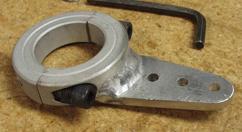
Here's a 1.25" ID alumimum collar clamp with a .188" thick 6061-T6 lever welded to it. I still need to do a little deburring on it. It has three holes which will provide quick and simple testing of the various theories on improving pitch sensitivity. The middle hole corresponds 1:1 with my elevator bellcrank spacing of 2.5". The other two holes allow a half inch of travel to test which way works best, and be altered in a matter of a minute or two. I'm using these same clamp collars on the flap torque tube (although .75" ID) to operate the flaps, without having bolts pierce the tube to potentially chafe the aileron cable, which runs through there on the "return" trip.
Here we are "almost" installed. The right stick is pinned for easy removal, and will be removed for most flights, unless I have a passenger who wants to fly. Total weight of everything but the four spar mounting bolts is 37 ounces, versus 13 ounces for the single stick setup as bought from RR (which uses the same 4 mounting bolts), so it's a pound and a quarter heavier than the single stick design. See the nylon fairlead epoxied into the mahogony gusset to the far left? That's where my aileron cable will come from, and connect to the turnbuckle. The sticks now pivot about the aileron axis very smoothly, eliminating the aileron cable stretching phonomenon common to KRs. Note how I had to mount the sticks entirely to the lower spar cap. If I could do it over again, I'd add extra spruce blocks inside the spar on 8" centers for the job, and leave the caps alone. That's what I did for the center stick, but that doesn't help me now.
The flap torque tube serves as the stop in the down direction. Electric jack screw is by "Motion", and is used on RVs. Stick is bent 20 degrees to dodge the flap torque tube. Stick hits spar at the same time the elevator bellcrank hits the flap torque tube, so we've got positive stops in the elevator down direction, and the carbon fiber seat will serve as stops for the elevator travel. I'm almost afraid to look and see how many hours this cost me, but it's well over a hundred. I think it'll do though!
I wonder how many KRs have their elevators "biased" by the aileron cables, and are trimmed out to compensate? I'll bet this is a major reason why some KRs are fast, and others are "not so fast"...
Return to Mark Langford's KR2S Project