Mark Langford's KR2S Project Cowling Page
Cowling Construction
Originally written July 14, 2001, revised Nov, 2014 (added some detail on cowling/firewall piano hinge connection)
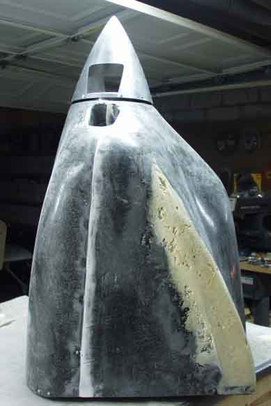
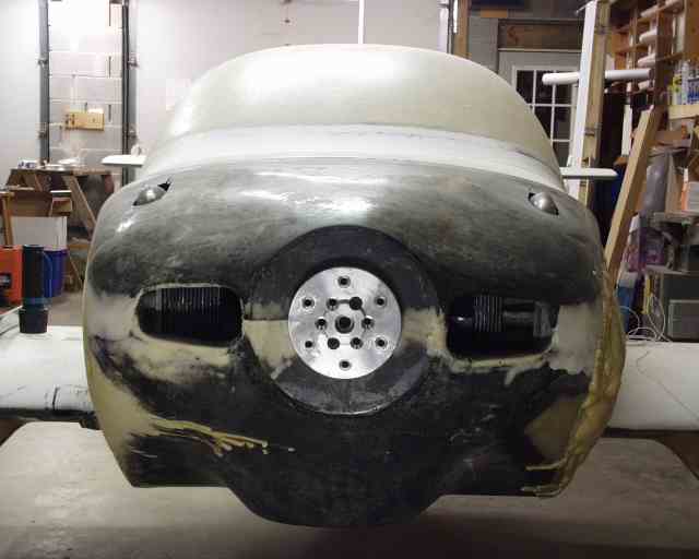
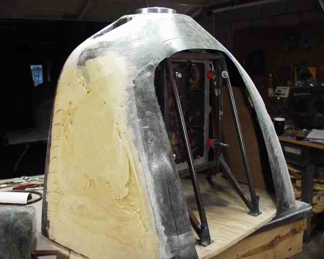
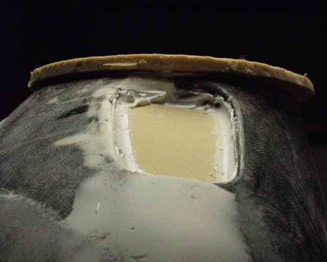
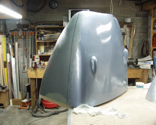
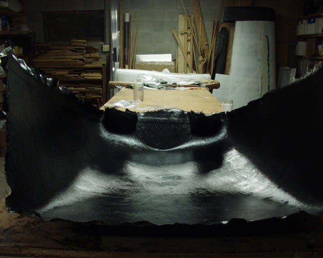
This is the beginnings of my cowling plug, which I made from a mold that I pulled off of one designed for the Revmaster and the KR2. It's made out of carbon fiber because for about a week or so I subscribed to William Wynne's attitude to "just get it done and go flying". I thought I'd just make this thing work and be done with it. But, since the KR2S is an inch and a half wider, and my particular installation is 3 inches taller than the stock KR2, I had to do a little surgery on it. The yellow stuff is two-part urethane foam, and the voids were caused by trying to squeegee the stuff into the gap. The other side turned out much better, since I turned the gap horizontal and didn't touch the foam once it was poured into place.
The interesting thing about this picture is the spinner. I was concerned about the flow from spinner to cowling, and have looked at several spinners trying to find a match. Troy Petteway let me borrow three of his, and this one is perfect! It's a 1-340-100 from Wag-Aero, (aka Aero-Fabricators), and it's their Cessna 150 spinner.
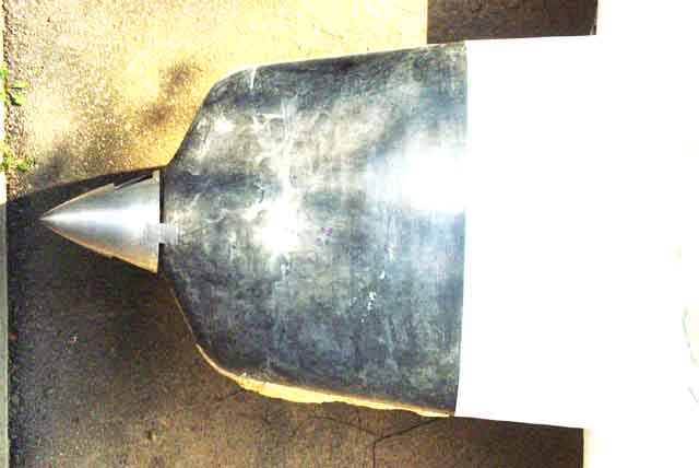
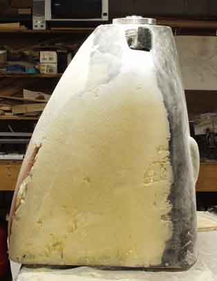
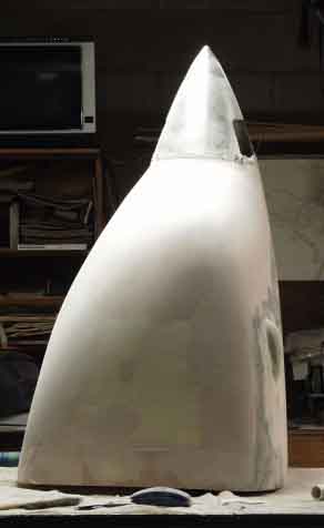
This is the view from the third story window of our house. You can see that there is a definite discontinuity between the profile of the cowling and the fuselage. I need to fix that...
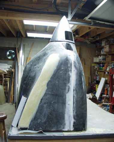
...and you can see from this that ugly is a definite possiblity here. The yellow stuff on the side is another layer of 2 part foam that I added to the "slab" sides to round them out a bit. The more I looked at it though, the more it looked like it needed more than a little rounding. The Revmaster is just not designed for the S or the Corvair. The lines just don't fit the plane, and there is clearance for things that don't exist on the Corvair engine.
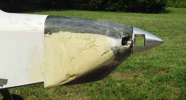
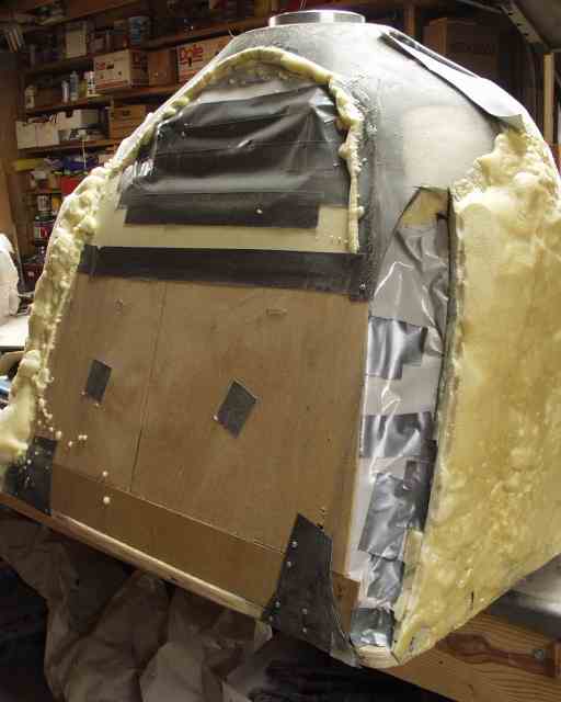
The overhang at the bottom is intentional on my part, since I plan to build in a NACA duct into foam glued and glassed to the bottom of the fuselage for exhaust and cooling air to exit (I got this idea from Troy Petteway's latest incarnation). There's a drawing of NACA duct dimensions in Tony Bengelis' yellow book, on page 200. I'll post a drawing of it after I CAD it for a full size plot.
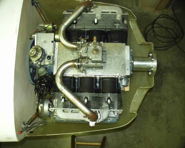
As you can see here, there's a good bit of extra room around the Corvair for the bottom of the Revmaster cowling. In fact, there's a lot of wasted space down there.
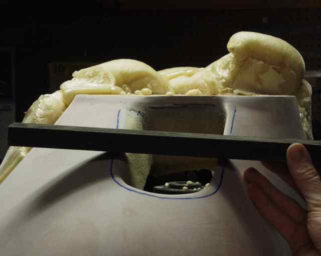
I needed a little clearance in the cowling for my intake manifold, although if I'd been smart I'd have simply milled the "integral" Corvair manifold off about 3/4" and made this a lot less noticeable. I may still do that [later I did exactly that].
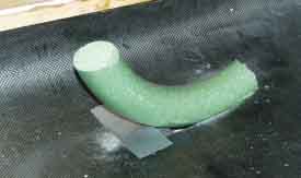
I thought about eyeballing it, but while at Walmart I found a styrofoam doughnut looking thing (presumably for Christmas wreaths) hat looked perfect for the job.
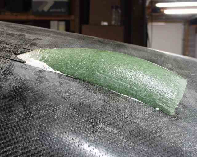
I microed a section of it in place...
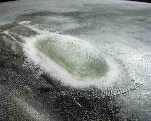
...and with a little work it became a "bump".
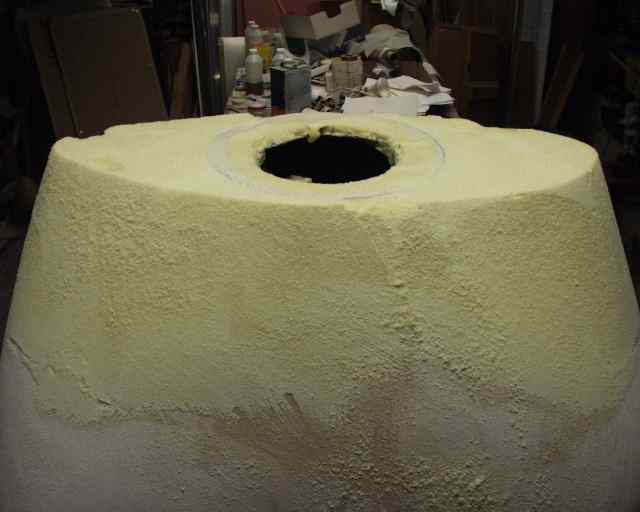
The more I looked at that bulge on the bottom, the less I liked it, considering that I didn't need ANY of it to mount my Weber carb underneath...so I exorcised it!
Doesn't this look a lot better? Well maybe not yet...
...but it's gettin' there!
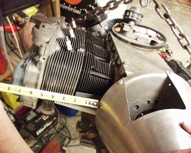
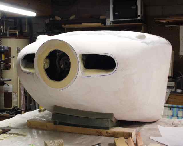
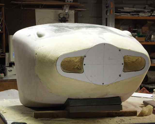
Next I started looking at the inlets, which are about 3.5" x 6" long, and offset from the spinner a half inch or so. It seems that the spinner should force air directly into the cowling duct, so I'll move the inlet over towards the spinner so that the opening and the spinner align. A quick check of the spinner/head relationship revealed that I only needed 5.75" wide inlets, so I'll shorten them and make them taller. Thorpe says allow .35 square inches per horsepower, so I'm shooting for 47 square inches (135 hp) total area, or 24" per side.
My inlets will need to be more squarish, and located higher up the cowling so as not to impinge on the front side of the cylinders, so hey, I might as well redo those too! I'm going to fill them in and completely redo them. Let's see, I think I have about one quarter of the original cowling left. It's a good thing I made it out of $200 worth of carbon fiber! While I'm at it, I might as well redo the spinner area and make my gap small and uniform, hence, the 3/8" urethane foam stuck on top.
Here's a back-to-back comparison. I think I'm improving it...
Inlets are slightly larger than the Revmaster, measuring around 42 square inches combined, compared to the Revmaster's 36 square inches, but then my Corvair engine will be putting out almost twice the power of the typical VW engine. Thorpe says use .325" per horsepower, which would put me around 45, but Paser is getting away with 30 square inches running a 160 hp Lycoming. I think I can eventually end up there too, but it's better to start big and then after testing and breakin, fine tune them to their smallest dimension. Troy did this using foam and duct tape until he got his inlets down to 20 square inches on his 2100cc VW engine. Note the ramps which will immediately direct the flow up over the front cylinders. Speed is a factor in these calculations, which is why I put more credence in Troy's and Pasers's numbers...they are going pretty fast.
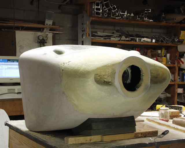
You know, as nice looking as the above cowling was looking, it still just wasn't good enough! What bothered me most about it was that I had managed to build the inlets such that the leading edge of the top was further aft than the leading edge of the bottom, mostly due to the much steeper contour of the top. Here you can see that my inlets were actually raked BACK at the top (the right, in this picture), rather than toward the BOTTOM for improved cooling during climb.
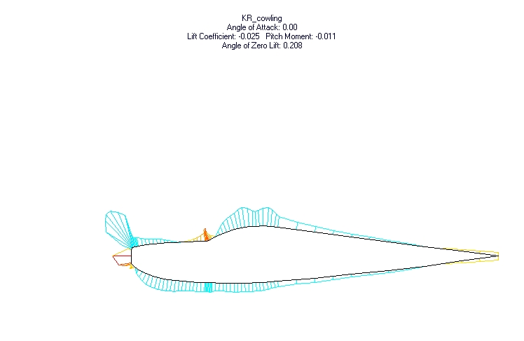
Richard Mole sent me this pressure distribution image of a cowling that looks very similar to a KR cowling. Notice the high lift over the top of the cowling, interfering with flow into the inlet. Although they don't actually show the shape and location of the inlets in this drawing (maybe there actually weren't any in this test), you can also see that the "bluff" part below the inlets (very close to vertical) are a real drag producer. And when the plane is climbing, the face that is presented into the "wind" is practically vertical, and the inlet area that the wind "sees" is decreased by the cosine of the angle of incidence, something like 3 percent at a 14 degree angle. That doesn't sound like much, but that's when you need your cooling most, so a 15 degree angle would maximize cooling during climb at low speed (100 mph), and reduce it slightly for cruise, where airspeed is much higher. Delivering more air to the duct than the engine can use for cooling results in the air coming right back out the duct, which is what I was seeing in the oil streaks coming OUT of the outboard end of Jim Hill's inlets.
Also, they were still larger than I will need. If Paser only needed 30 square inches for 160 hp, I know I won't need even that much, especially considering the efficiency of the NACA duct cooling outlet that I'm planning.
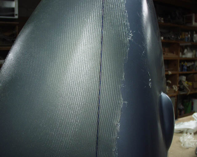
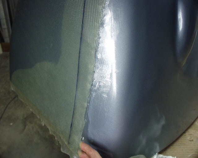
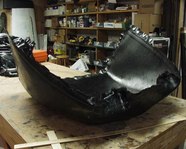
So I started over! But as you can see by the above photo, it didn't take long to regret not having pulled a mold off of that beautiful cowling that I'd had before.
It took me a week to decide whether or not to go with the new round inlets that are are in vogue on newer spam cans, Lancairs, LoPresti planes, etc. I'm sure they are more efficient (research was done by Mississippi State, funded by NASA), but given the geometry of the Corvair engine (very narrow, due to the short stroke), the ducts HAD to be adjacent to the spinner, and very compact. This sends some of the high pressure spinner air into the duct and allowed a very small frontal area with more streamlining back to the "body" of the cowling. I may build a "holey cowl" later on just to see what happens, but for now, I'm trying to improve on the more conventional inlets.
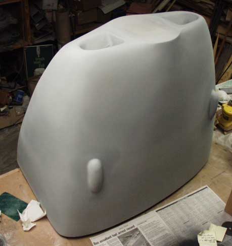
Another thing that had bothered me about the previous cowling was that it was very difficult to get the inlets oriented the same with respect to each other. This time I vowed to try for perfection and drew up a template to sand to.
I think this will be an improvement. The inlet areas are reduced again, down to 19 inches each, or 38 square inches total. I'm still confident that this will be more than enough for the Corvair, even considering that the stock Revmaster has 36 square inches of inlet area. After all, Marty Roberts is flying a Revmaster cowling with well over 120 hp. After I'm flying, I'll "choke" it down more, using foam and duct tape, to reduce it to the point where maximum speed is achieved and cooling isn't decreased. And thanks to the template, they are at least identical and symmetrical.
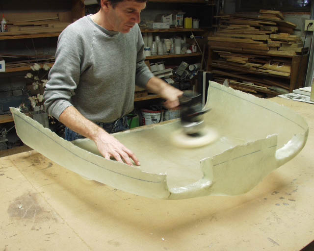
At this point the cowling plug is smooth enough for "prime time" and has one last layer of Featherfil to sand down. That should only take an hour or so with the palm sander, although it'll take 3 days to clean up the resulting mess.
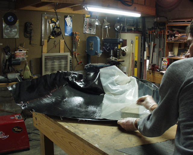
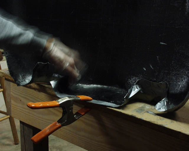
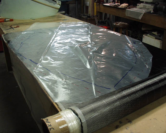
Next I shot a layer of DuPont Centauri acrylic enamel paint on it (just for practice, and to give a slick finish) which I'll wax and coat with PVA (polyvinyl alcohol) and lay up three or four layers of glass to make a mold. Another round of wax and PVA and I'll layup two layers of carbon fiber to make my real cowling, which will weigh right at 4 pounds. Then I'll be able to retrieve my engine mount from within the plug, mount my engine, and get on with this stuff.
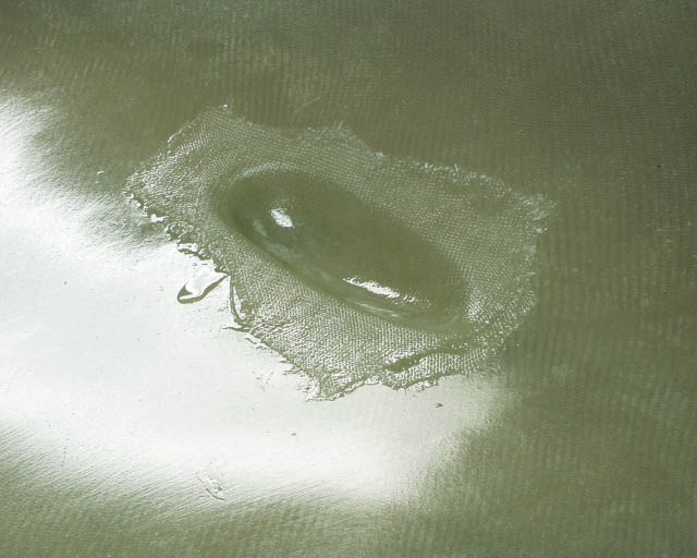
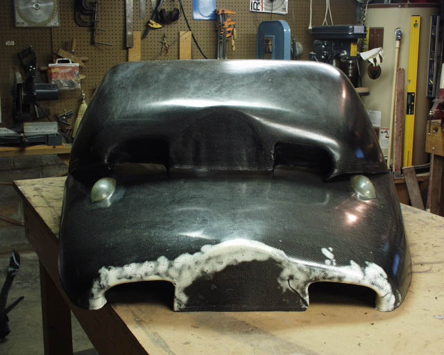
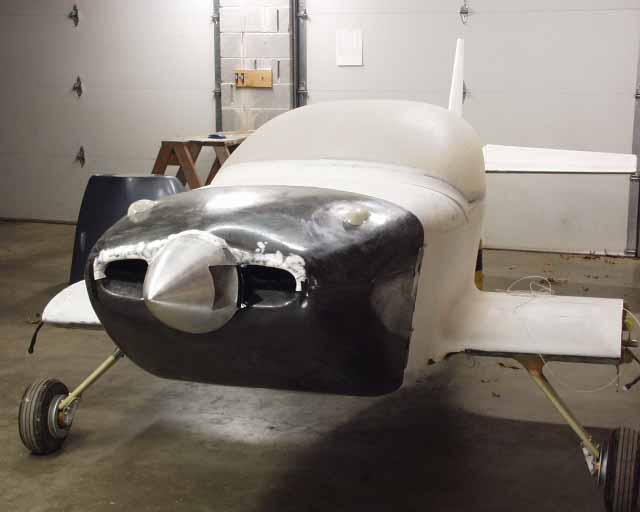
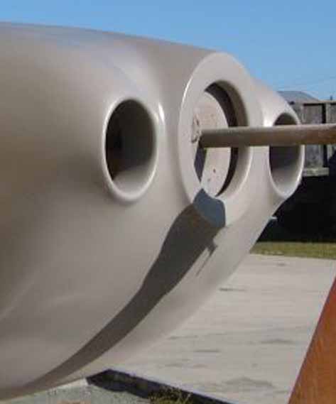
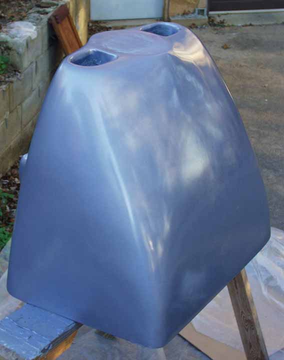
Here's the final product. Not too bad, huh? It's just stuck on with duct tape at the moment, although the engine is actually installed, and the fit is amazingly good. It is well blended into the fuselage, although it's hard to see that from this photo. Keep in mind that I left 2.5" of space at the bottom for exit area which will blend into the fuselage with a NACA duct for exiting cooling air and exhaust. The white stuff around the top of the inlets is a flox/micro mixture that I used in the mold to assure full contact with the carbon fiber and the mold. Although it looks kinda ugly in the photo, it's really smooth. The little air intake clearance blisters on top were glassed rather than carbon-fibered because the glass is more flexible and conformed better. Any resemblence betweeen the blisters and front turn signals on an early 60's Beetle is purely coincidental.
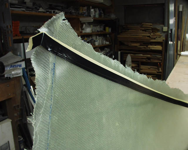
Last night I trimmed the two parts down to shape with a Dremel cutoff wheel. Over the weekend I'll work to install the piano hinges that will join top to bottom half (while on the workbench) and then it'll be a matter of fastening the whole thing to the airplane. While I'm at this stage, I think I'll go ahead and install the fiberfrax and stainless steel firewall material, and start doing things for the "final" time, rather than trial-fitting.
Update, Nov 2014 - added some detail on the piano hinge attachment to cowling halves
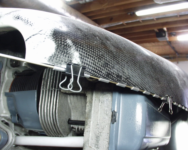
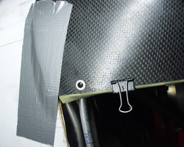
I started the piano hinge mounting with some "binder clips" from the local office supply store.
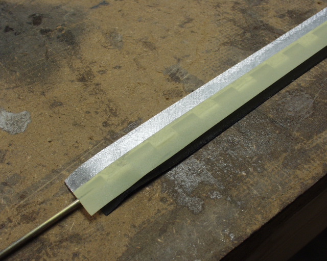
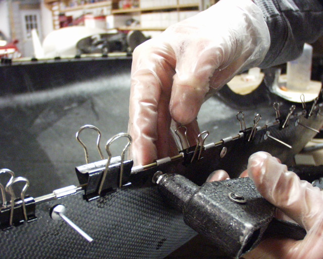
I taped over the critical circular part of the hinges to keep the epoxy out...otherwise the pins would bind going through there. I used some thin 3m painter's tape, but electrical tape or packing tape would have worked too (although packing tape is bad about tearing and becomeing painful to remove).
I also had to protect the other side, so it got some electrical tape.
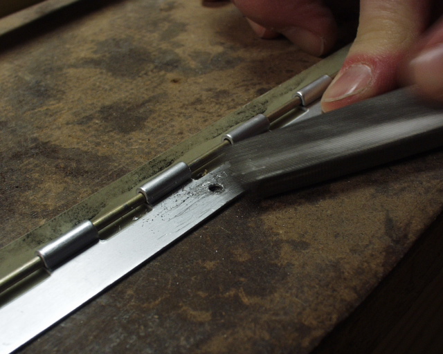
I'd already drilled holes on an interval along one side of the hinge, so I deburred them the primative way...with a file. I also roughed up the whole surface with some 60 grit sandpaper to improve adhesion with the epoxy.
I reinstalled the upper hinge with the binder clips (and taped-over hinge pin area), and a screw in each end to keep the hinge from shifting while match drilling.
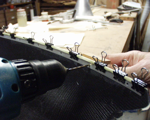
Then I match drilled the cowling using the holes I'd layed out on the bench and drilled into the hinge.
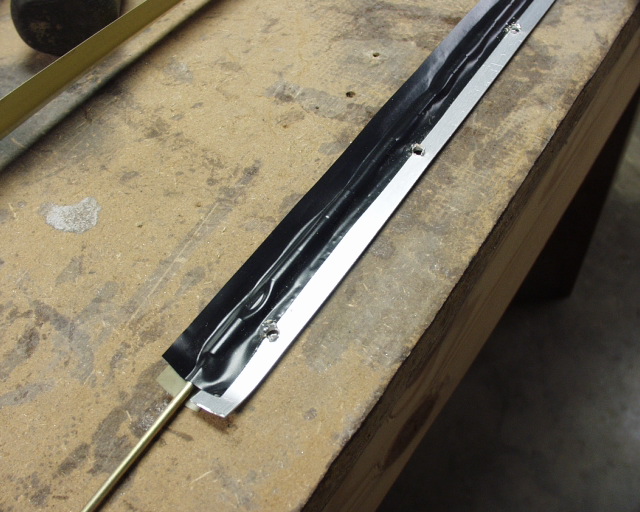
Then I put some epoxy/flox mixture on the inteface between cowling and hinge, and pop riveted the hinge to the cowling, using large-diameter low-profile rivets, and a backup washer on the inside. This was only two layers of carbon fiber, so I was squeamish about countersunk rivets, although I used them on the other side and they worked fine. A little palm sanding, a 1" wide glass tape, and some filler, and even these low-profile rivets disappeared for good.
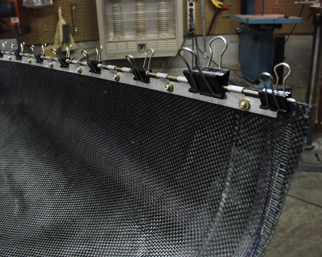
20/20 hindsight tells me the backup washers were certainly overkill as well.
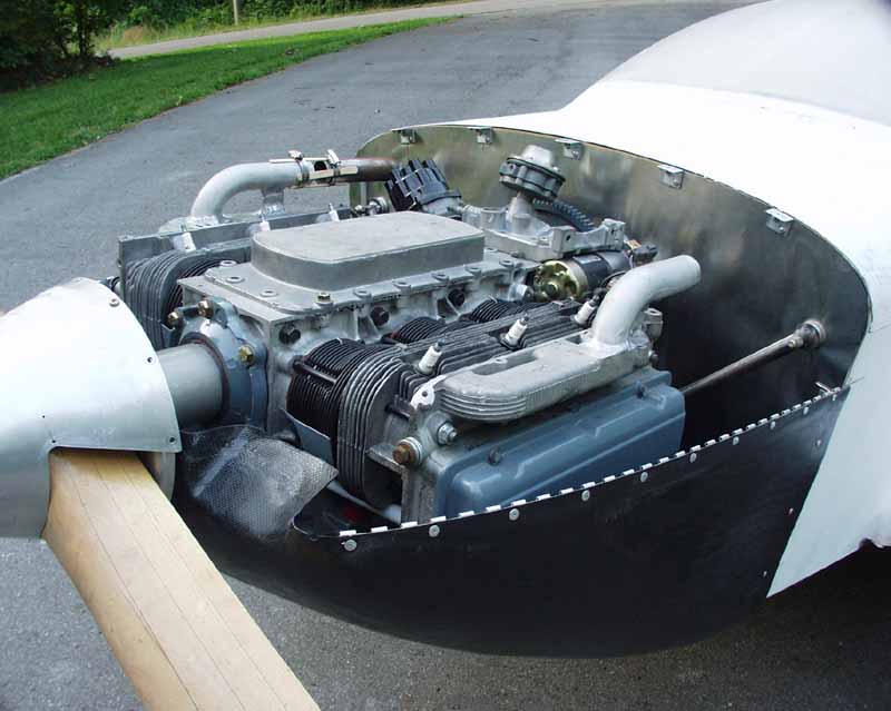
Since I was able to use just two layers of carbon fiber, the whole thing weighs under 3.7 pounds, compared to eleven for a Revmaster KR2 cowling.
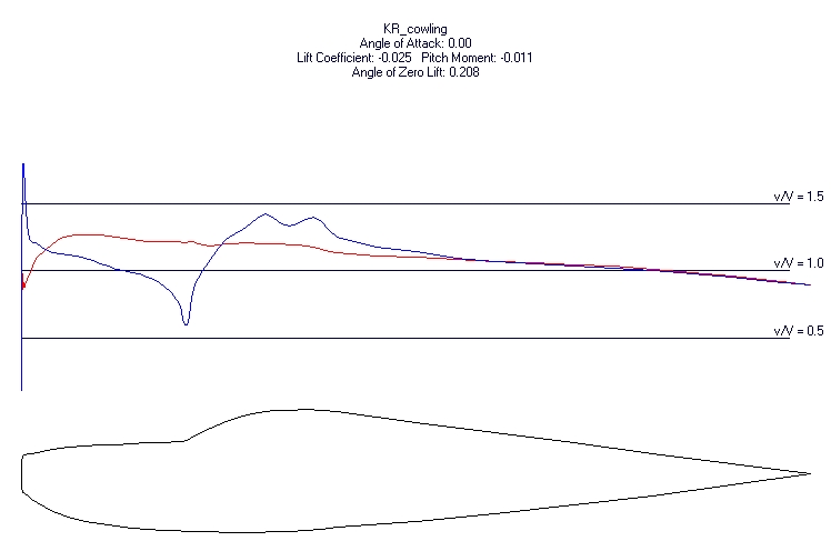
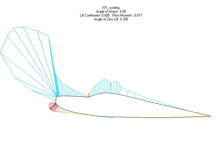
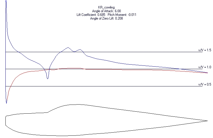
Below are some pressure distribution plots that Don Reid send me, based on my side view drawing and his pressure distribution (airfoil) software. The take home point is that intakes located up high are under negative pressure, but slightly below the centerline of the spinner it's a very high pressure area. Food for thought when designing my next cowling...
Return to Mark Langford's KR2S Project