Mark Langford's KR2S Project


Corvair Intake Manifold

written January 27, 2002 updated September 13, 2005 (added bolted elbow connections at bottom)


Here's a steel intake runner that I made from 1.5" diameter steel tubing. This is a mandrel bent 2" radius "U-bend" ($6) from Magnum Force Racing, welded to a laser cut 3/16" thick flange. What I didn't like about it was the tight bend radius and the wasted height of the Corvair's stock flange. Also, the stock flange hole diameter is only about 1.315", and the tubing ID is larger, so there was a step there that I was reluctant to smooth over because I wasn't sure I'd be able to prevent aluminum chips from hiding in the intake.


I milled off the stock flange and welded one of Burns Stainless' 16 guage 6061-T6 U-bends ($22)directly to the head (after cutting it in half). I'll also weld a gusset between the left end of the tube and the manifold log to minimize the bending loads on the weld (I just ran out of Argon). This arrangement saves me about half an inch in height (and a bump in my cowling), the weight of the flanges and fastening hardware, the lighter weight of aluminum vs steel, and gives me a larger radius bend for the intake system. I also radiused the inside of the pipe and it's stuffed down inside so that end of the tube is flush with the inside of the manifold to smooth the airflow somewhat better than what GM bothered to do. This welding isn't the prettiest, but I did it myself, heating the head and pipe to 300 degrees and TIG welding it. I practiced on a junk head, beating the joint to oblivion, and it's still welded! The downside of this welded joint is that you're stuck with this configuration. A bolted joint is a lot easier to try different setups on.

The stock flange is 7/8" tall, so if I'd done nothing more than milled it off and welded a piece of quarter inch aluminum back to it, I'd have saved 5/8" off the height, and the weight of the stock tall flange. After the engine is thoroughly tested and I start looking for something to do, I'll machine the whole intake log off and weld in three runners in it's place, similar to tube headers, but for the intake. I'll keep the same carburetor and other manifold tubing. I just want to see if there's a tangible difference when dispensing with this goofy GM "log". I suspect there IS!

In other news, the main reason I had the heads off was primarily flip the pistons over. I'm convinced that the arrows on the VW pistons need to point toward the pulley (since this engine spins reverse from a VW) rather than toward the flywheel to minimze piston slap, so it was important to me to get that right. At the time I installed them I was following Bob's instruction sheet, which I now suspect was designed for Corvair sand-dragsters running reverse rotation engines.

While I was at it, I lowered the compression ratio to 8.5:1 (down from 9:1), since I want the option of running 93 octane auto fuel. I'll be flying to my father's sod strip quite often, and last time I checked he didn't have any 100 LL! Besides, I don't need lead deposits and sticky valves. During testing, I'll see if I can get away with 91 octane, and if so, I'll try 87 octane. If that's not a problem, I'll go back to 9:1 the first time the heads come off. I'd never consider running anything less than 93 octane (it's easy to find in this neck-of-the-woods), but want to make sure that I can afford the bump up before I go back to 9:1.


Here's my Weber 40DCOE sidedraft carb mounted below the engine. You can see that I used a bent up sheet of 6061-T6 aluminum, fastened by the same bolts that hold the engine to the mount. Rubber isolators would probably be a better idea, and will probably come later.


The nuts are just bosses welded onto the back side of the bracket. Intake hoses are joined by 1.5" fuel hose with two joints on each run, to reduce the possibility that vibration from the engine will cause fatigue to crack the aluminum intake where the tubes are welded to the flanges.


Here's the final product, complete with support gussets. I'll confess that these welds are the very definition of "poor welds", but it's the best I could do at the time. Part of the problem was trying to weld a thin strip to a thick manifold. Preheating the head would have helped, as well as choosing a thicker gusset material.

I will probably end up cutting all of this mess off someday and redoing it completely. The funny thing is that if the tubing breaks at the weld joint (and fatigue may very well cause that eventually), I'll probably go back to the steel flanged tube, and weld on a new flange to the intake manifold. This would be far less susceptible to fatigue, would weigh only slightly more, and be about the same height, since the steel tubing has a sharper bend than the aluminum tubing.


August 1, 2004 - Ellison intake manifold construction.


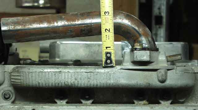
Here's the beginning of the Ellison manifold, two 1.5" outside diameter 16 gauge 6061-T6 45 degree tubes bought from
Burns Stainless', and chopped to meet in the middle.


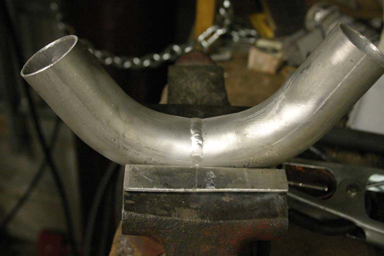
The tubes were then welded together as best I could...


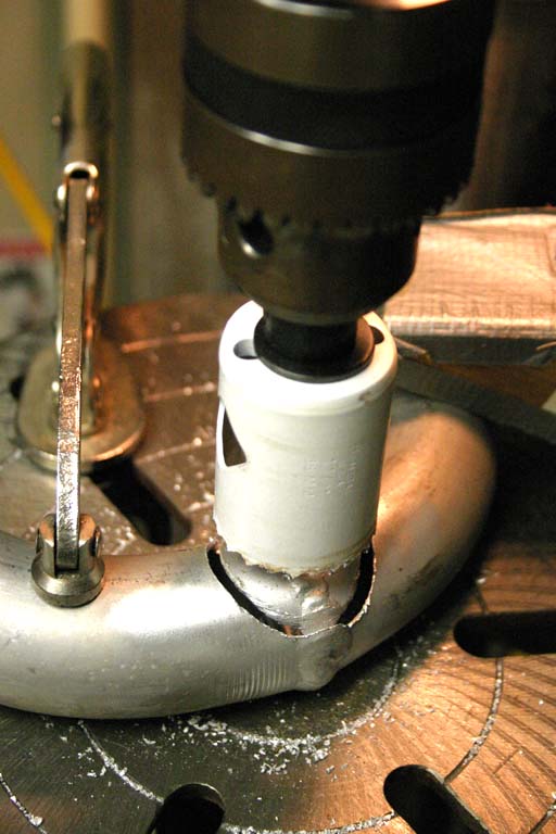
...and a 1.5" hole drilled in them with a worn-out hole cutter.


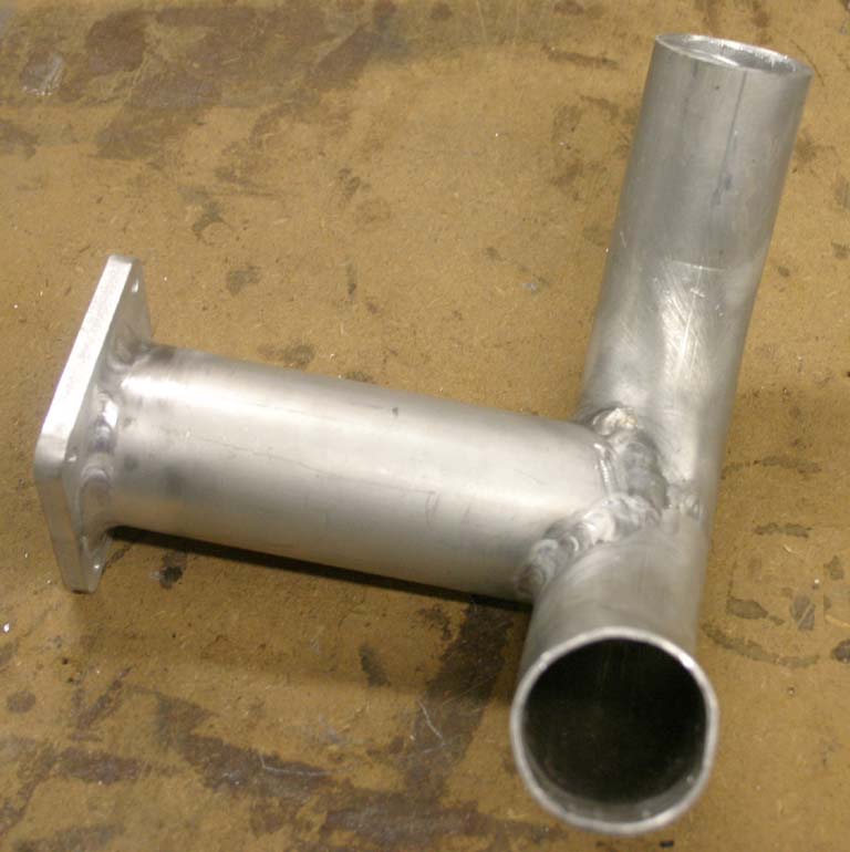
I then opened it up into an oval shape to match the 2" tubing that I'd squashed into an elliptical shape, and welded them together. The flange shouldn't be in this picture, since it actually came later, but it was just cut out of quarter inch 6061-T6 on the band saw and the holes were made with the same cutter and drill bits.


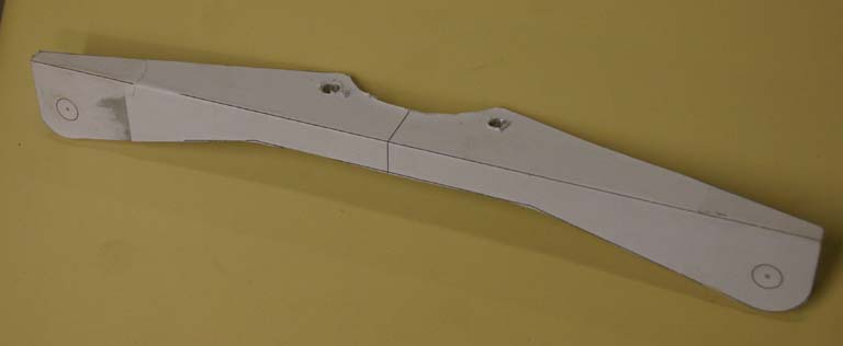
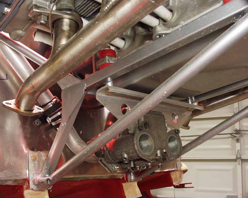
I needed a bracket to hold the carb up, do I laid one out in CAD, printed a full size template, glued it to a piece of 1/8" aluminum angle, and cut it out.


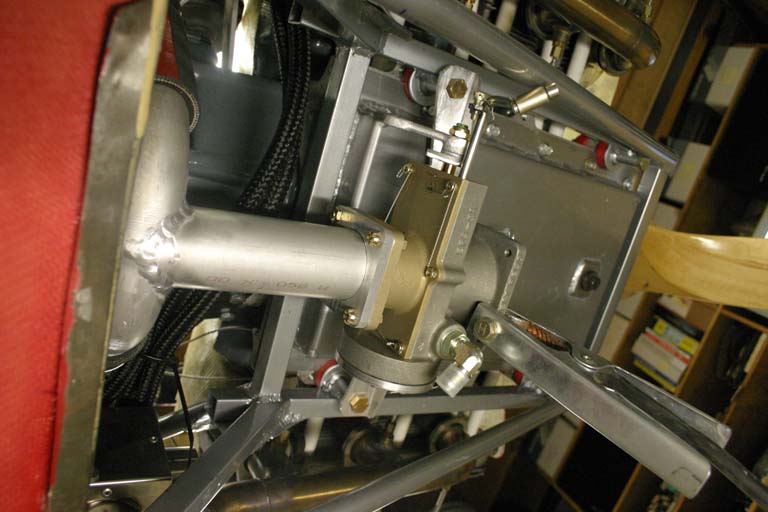
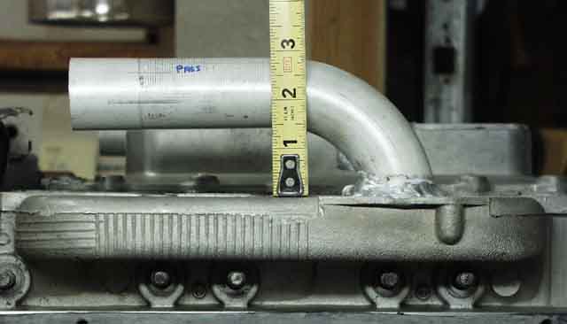
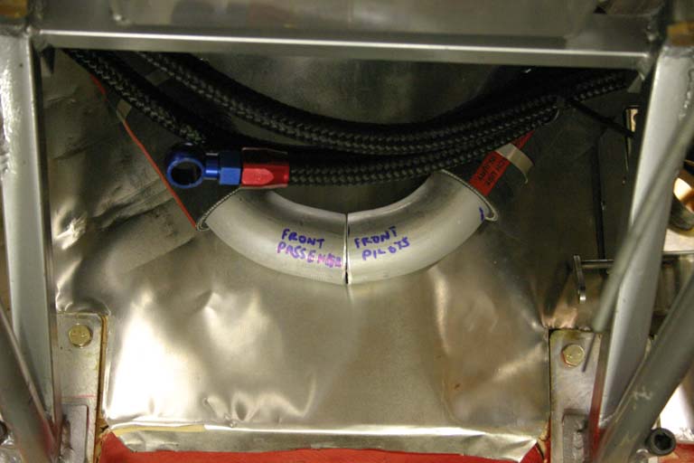
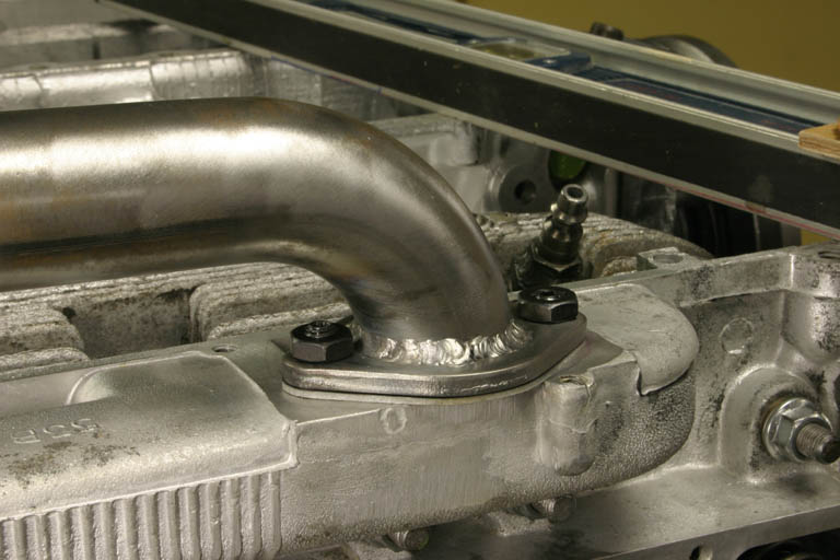
Now that I had a bracket, I could mount the carb and tack the flange to the rest of the manifold. As you can see, I made the tube from the carb to the vertical portion of the manifold a full 6" long to help promote better attomization before the fuel "hits the wall" and is forced to go vertical. This seems to have fixed the fuel pooling issue, although it could be argued that the Ellison itself fixed that, compared to the Weber. This is probably overkill though, and I probably should have made it something like 3", so I'd have more room for the airbox.


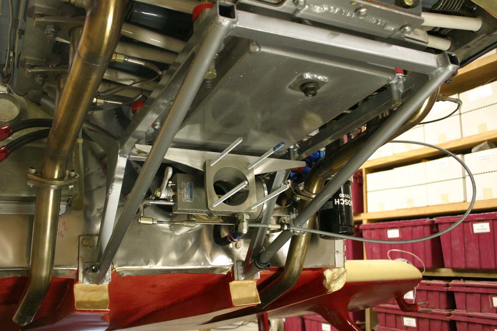
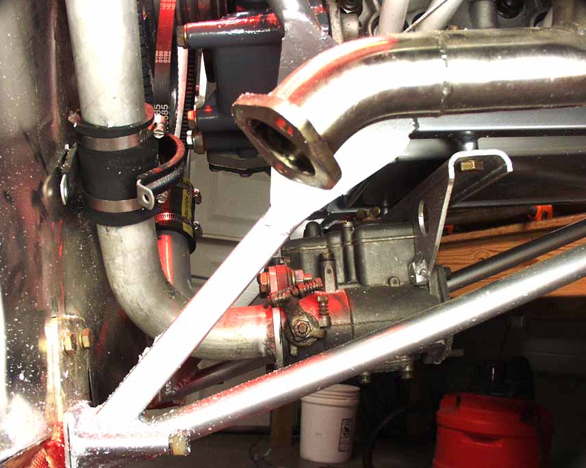
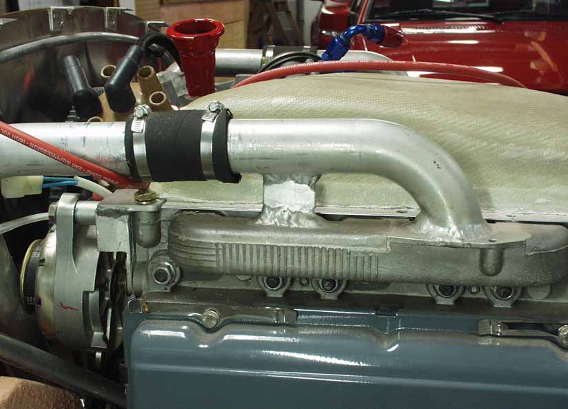
Here it is installed, except the throttle cable is a cobbled-up affair for testing and the mixture isn't installed at all yet.


Later, when I built my 2700cc engine, I bolted my intake tubes on, rather than welding them. This allows me the versatility to do things like change to a turbo or different intake setup, as well as allowing me to have a spare head that will fit either side of the engine. And the biggie for me is being able to clean debris out of the intake log after valve grinding or similar events, as well as being able to clean up the entrance port. When welding the intake tubes directly to the head, you have no idea what kind of penetration you're getting with that cast material (which is not that easy to weld anyway), and you don't know if you've put a big blob of stuff in there that will impede flow in one direction or the other. Welding up a flanged tube and bolting it in place solves these problems, but introduces a new one of proper sealing under all conditions. William Wynne says he's had lots of problems sealing bolted flanged connections, which is why he now welds them all. I'm going to have some special three bolt flanges made (either laser or waterjet cut) to help solve that problem, but that will come later.


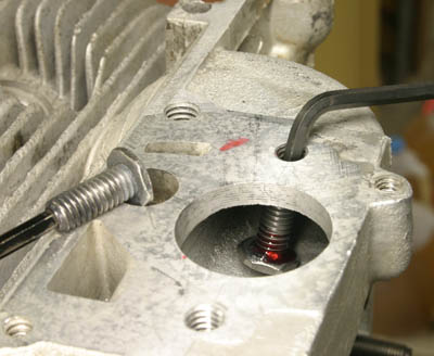
I made the studs from allen studs with low height nuts welded to one end and ground sort of rounded, just short enough to stand up inside the manifold. Then I used red Loctite on the allen wrench to allow me to pull it up and start in in the hole. The second one shows the final installation. 20/20 hindsight says I might just take a grade 5 hex head bolt and drill a hole in the threaded end to replace the allen head hole, epoxy an allen key into the end of it as shown in the first shot, and then do the same thing with it. The thought of that low-height nut bouncing around in the cylinder scares me a little. Although it IS welded to the stud to keep the stud from pulling out, it could break loose, and the heat treat on the stud is now compromised by the welding. I'd also like to make some thinner flanges so I have enough room for a locknut. Steel flanges are about a buck a piece from Bugpack (for Volkswagens) and the tubes are U bends from http://www.magnumforce.com/ubend.asp for $8, cut in half and welded. Grand total for the setup is ten bucks. I cut the carb flanges off with a reciprocating saw and then flattened pretty well with a belt sander, but since Ray was resurfacing the head gasket surfaces on his mill, I asked him to flatten them while he was at it. That's the beauty of the bolted flange...I can change it next week if I feel like it. I always have access!

Later...July 2007

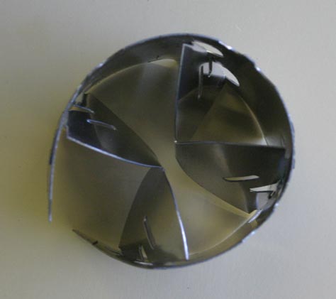
One thing I added later was a Tornado "fuel saver", a gizmo that probably doesn't actually save much fuel, but really does stir up the air and fuel just past the carb base, so it's more thoroughly mixed when it gets to the vertical split that wyes off to left and right heads. This thing really does work, as my EGTs got much closer together after installation, from 175 degree spread to a 25 degree spread when running carb heat. They are about $50, and available from www.tornadofuelsaver.com. I just slipped it in, drilled a hole, and pop riveted on rivet in there to make sure it doesn't go anywhere.


Return to Mark Langford's KR2S/Corvair Page