Preliminary results from the wind tunnel tests for the AS5045 and AS5048
airfoils
Ashok Gopalarathnam and Michael Selig, 7 July 98
Summary of the main design goals for the AS5045
and AS5048 airfoils
Table 1 The main design goals for the two airfoils
|
AS5045 |
AS5048 |
| t/c |
15% |
18% |
| Cd at cruise (Cl = 0.1, Re = 5.6 million) |
<0.005 |
<0.005 |
| Clmax (Re = 1.5-2 million) |
1.3 |
1.25 |
| Clmax |
not dependent on extensive laminar flow
(not highly sensitive to roughness) |
not dependent on extensive laminar flow
(not highly sensitive to roughness) |
| Cmo |
-0.055 |
-0.06 |

Soon to come: AS5045 and AS5048 airfoil geometries and coordinates
Brief description of the experimental setup
The UIUC 3x4 ft. open-return, low-speed wind tunnel was used for the experiments.
The high-quality airfoil models with excellent surface finish and smoothness
were made by Steve Eberhart.
The 18" chord models were mounted vertically on to the tunnel balance on
the floor. Lift and pitching moment on the model were measured using the
balance. Drag was measured using a wake rake.
The models have not yet been digitized. We expect to digitize the models
using a coordinate measuring machine in September 1998. No wind-tunnel
corrections have been applied to the data yet.
The key focus of the tests were to obtain experimental verification
of the Clmax, stall characteristics and the effect of roughness
on the stall behavior. Owing to limitations on the maximum tunnel speed,
the maximum Re that could be achieved with an 18" chord model in this tunnel
is around 1.8 million. For the airplane wing, this Re corresponds to the
Clmax condition. Re values for cruise condition for the wing
in flight are much higher than 1.8 million, and cannot be measured in the
tunnel.
Acknowledgments
Ashok would like to gratefully acknowledge the invaluable assistance provided
by Sam Lee and Andy Broeren during these tests. Without Sam's help in adapting
his data acquisition code to suit the current experimental needs, the data
presented in this page would not exist. Andy spent several hours of his
time helping Ashok get up to speed with the flow-viz and model installation.
Ashok would also like to thank B.J.Jasinski and Philippe Giguere for their
help with installing and changing the models.
Results for the AS5045 (15%) airfoil
Figure 1 (repeat_1m.gif) shows the lift, drag
and moment characteristics for the AS5045 airfoil at a Re of 1 million.
(The data shown is from two different runs to check repeatability). Figures
2 (repeat_1-5m.gif) and 3 (repeat_1-8m.gif)
show the data for a Re of 1.5 million and 1.8 million. As seen from the
figures, the data is repeatable.
The following observations can be made from the figures:
Table 2 Summary of the AS5045 airfoil performance from
the tests
|
Re (million)
|
Clmax
|
amax (deg)
|
Cm (nominal)
|
Stall type
|
|
1.0
|
1.2
|
~14
|
-0.05
|
gentle
|
|
1.5
|
1.25
|
~14
|
-0.05
|
gentle
|
|
1.8
|
1.28
|
~14
|
-0.05
|
gentle
|
Note that although the data is shown for Cl values from -0.4
to stall and beyond, the only data relevant for the airplane is the data
close to stall. In other words, the Cd values from the data
at low values of Cl are quite irrelevant. This is because at
the speeds corresponding to the airplane climb and cruise conditions, the
airfoils on the wing operate at Reynolds numbers much higher than 1.8 million.
(See the web page on reduced
Re for information on the variation of Re with flight speed and CL
for the KR-2 type airplanes). The limitations on the tunnel speed, however,
prevented us from testing the airfoils at Reynolds numbers greater than
1.8 million. The airfoil Cd at flight Re corresponding to cruise
and climb should be significantly lower than those shown in the above data.
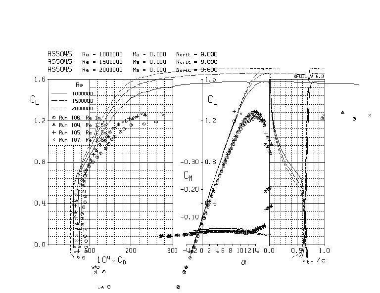
Figure 4 (test_res1.gif) compares the data
for Re of 1, 1.5 and 1.8 million with the results predicted by XFOIL for
Re of 1, 1.5 and 2 million. It is seen that the Clmax is much
less than that predicted by XFOIL. This behavior was expected. It was known
even before the design of these airfoils that XFOIL consistently over predicts
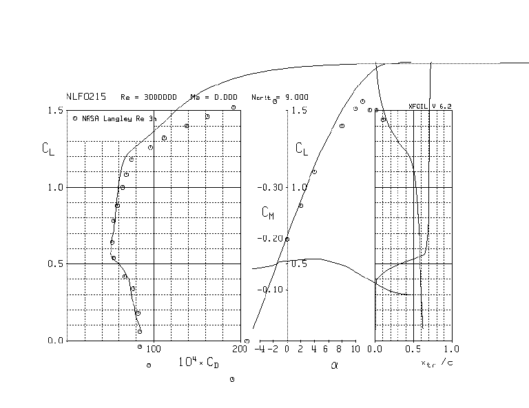
Clmax (at least for airfoils of this class). For example, Fig.
5 (compare_nlf0215_3m.gif) compares
the XFOIL predictions for the NASA NLF(1)0215 airfoil with the experimental
results from tests done at NASA. While the XFOIL predictions for the low
Cl agrees quite well with the NASA data, the XFOIL predicted
value of Clmax is about 0.25 higher than that obtained from
experiments. Other comparisons (not shown here) show that the XFOIL-predicted
Clmax is sometimes up to 0.3-0.4 higher than that obtained from
experiments. During the design of the airfoil, this tendency of XFOIL to
over predict Clmax was taken into account and it was expected
that the airfoil Clmax would be around 1.3-1.4. The more important
design goals related to stall were that the stall be gentle and that Clmax
of this airfoil be not less than that of the RAF-48 and the NLF(1)0115.
Because experimental results for the RAF-48 and the NLF(1)0115 are not
available, it is not possible to verify this goal. It is expected that
although XFOIL over predicts Clmax, the differences in Clmax
from one airfoil to another should still be correctly predicted. As shown
in the web page
on the design of these AS airfoils, these goals have been satisfied
(based on XFOIL predictions for the AS5045, the NLF(1)0115 and the RAF48
airfoils).
Effect of leading-edge trips on the AS5045 performance
To test the effect of leading-edge roughness on stall characteristics,
the performance of the airfoil was tested with leading-edge trips. Three
types of tape were used:
Table 3 Types of trip tape used for the current study
|
Trip number
|
Trip type
|
Trip height
|
Trip width
|
Trip location (aft edge of tape)
|
|
1
|
4 layers of ultracoat
|
0.009"
|
0.2"-0.25"
|
2% x/c on upper surface
5% x/c on lower surface
|
|
2
|
1 layer of "DYMO" adhesive labeling tape
|
0.009"
|
0.38"
|
2% x/c on upper surface
5% x/c on lower surface
|
|
3
|
2 layers of "DYMO" adhesive labeling tape
|
0.018"
|
0.38"
|
2% x/c on upper surface
5% x/c on lower surface
|
Figure 6 (trip1_2_re1-8m.gif) compares
the clean performance of the AS5045 airfoil with the performance with trip
configurations 1 and 2 at a Re of 1.8 million. It is seen that with the
smaller trip (Trip 1), the Clmax of the airfoil drops by about
0.06 compared with the clean case. With the wider trip (Trip 2), the drop
in Clmax is about 0.15. Figure 7 (trip1_2_3_re1-8m.gif)
compares the effect of the large trip (Trip 3) with the clean case and
the smaller trips for the same Re of 1.8 million. With the larger trip,
the drop in Clmax compared with the clean case is about 0.2.
Also seen is that for all the trip configurations, there is a significant
increase in drag. This increase in drag is a consequence of the loss in
laminar flow resulting from the forced transition. A part of the drag increase
can also be attributed to the "device-drag" of the trip itself.
These results emphasize the need to keep the wing (the leading edge
in particular) free of bugs and contamination. While it is hoped that small
roughness elements will not significantly decrease Clmax, there
is a decrease in Clmax with increasing size of the leading edge
roughness. This decrease in Clmax with increasing size of the
roughness element is expected. The design philosophy used for the AS5045
and the AS5048 minimize this decrease in Clmax with increasing
roughness size. For this reason, it can be expected that the stall speed
will increase with large roughness (in rain, for example). For example
a decrease in Clmax of 0.2 results in a stall-speed increase
of roughly 5 mph. Therefore, airspeeds should be increased by at least
5-10 mph when flying close to stall in rain or with leading edge roughness.
Results for the AS5048 (18%) airfoil
The AS5048 airfoil was tested at Re of 1.0, 1.5 and 1.7 million. This airfoils
could not be tested at Re values beyond 1.7 million because of problems
arising out of interference between the model and the tunnel floor at high
loads. Only the results for Re of 1.5 million and 1.7 million are presented
here.
Figure 8 (as5048_1-5m.gif) and Fig. 9
(as5048_re1-7m_repeat.gif)
show the performance of the AS5048 at Re of 1.5 million and 1.7 million
respectively.
The following observation can be made from the figures:
Table 4 Summary of the AS5048 airfoil performance from
the tests
|
Re (million)
|
Clmax
(drag rise)
|
amax (deg)
(drag rise)
|
Cm (nominal)
|
Clmax
(peak lift)
|
amax (deg)
(peak lift)
|
Stall type
|
|
1.5
|
1.15
|
~13
|
-0.045
|
1.28
|
~16
|
gentle
|
|
1.7
|
1.15
|
~13
|
-0.045
|
1.25
|
~15
|
gentle
|
A peculiar feature that can be seen from the reults for the AS5048 is that
although the Clmax corresponding to the maximum in the lift
curve is around 1.25-1.28, the drag rises to significantly high values
at a Cl of around 1.15. It is felt that this behavior is due
to large trailing-edge separation at Cl of 1.15, causing high
drag, but the lift continues to increase with increasing a
till around 1.25. It is felt that the actual Clmax for this
airfoil (as "felt" by the pilot) at these Re values will be around 1.15-1.2.
Figure 10 (as5045_48_re1-5m.gif)
compares the experimental results for the AS5045 and the AS5048 with XFOIL
results for the airfoils at Re of 1.5 million.
Effect of leading-edge trips on the AS5048 performance
Owing to lack of time, the effect of trips for this airfoil were investigated
only for one trip size (the large trip # 3). Figure 11 (as5048_re1-7m_trip.gif)
shows the effect of using the large trip (Trip 3) on the performance of
the AS5048 airfoil at Re of 1.7 million. It is seen that the drop in Clmax
is around 0.25, which is a larger drop when compared with that for the
AS5045.
Recommendations
The following recommendations are made regarding the use of the AS5045
and the AS5048 airfoils on the modified KR-2S airplanes:
-
The gentle stall characteristics of the 15% AS5045 make it an ideal choice
as an airfoil for the entire wing.
-
If it is desired that a higher thickness section be used at the root for
structural considerations, the AS5048 at the root in combination with the
AS5045 outboard form a good combination. The earlier stall and trailing-edge
separation of the AS5048 when compared with the AS5045 can prove beneficial
in providing the pilot with good stall warning.
-
However, the early trailing-edge separation at high Cl can also
result in high interference drag penalties. This fact must be kept in mind.
-
It is felt that the AS5048 may not be a good choice for the outboard wing
portions, where early trailing-edge separation may reduce aileron effectiveness.
This page has been accessed  times since 7 July 98.
(Design
page for the AS5045 and the AS5048 airfoils)
(Steve Eberhart's page on the airfoil
models for the tests)
(
Mark Lougheed's CFD analysis of the AS5045 airfoil)
(Ashok Gopalarathnam's
page)
(UIUC
Applied Aerodynamics page)