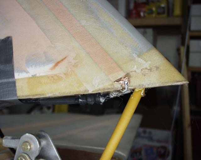
The antenna is a dipole consisting of a piece of 20.3" long 1/2" wide copper tape laminated into the leading edge of the vertical stabilizer, and a matching length rolled up into an arrow shaft (available from Wicks)as the bottom leg. Although the connection can be either way, mine has the center conductor going the the upper foil tape, and the shielding twisted together and soldered to the bottom leg of tape. Some hot glue, micro, and fiberglass tape over the connection have prevented the connection from breaking loose so far (650 hours, July of 2008).
This location violates the rules of trying to keep the dipole legs away from cables and large metal objects, but it's the only place tall enough to put the thing, except right behind the seat. I'm paranoid enough without putting an antenna behind my head. This antenna works well enough to pick up planes in the pattern at Cullman, 40 statute miles away, and this is from inside my basement! And lots of KR folks are using this same setup, with great results. There are more details on this system, as well as a lot of other handy electronic projects, located on RST Engineering's web site.
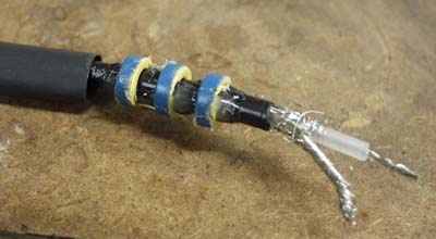
The coax uses RST's toroids as a "balun" on the antenna end. The toroids were hot glued in place, and then shrink tubing secured the installation.
After my installation was complete, a short-wave radio buddy from work (who just happens to be an electrical engineer) came over to check the SWR for me. He hooked it up and twisted knobs for about 30 seconds, then announced in a reverant tone of voice "don't touch a thing, it's perfect like it is"!
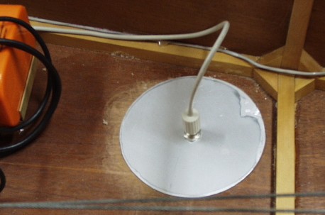
The transponder antenna uses a 5.5" piece of aluminum for a ground plane and reinforcing plate. Antenna cable is from a stranded 10-base2 network installation. This way I KNOW one end is properly installed. Don't use regular "television cable" cable. It's not the same thing, and has the wrong impedence. Use RG-58AU (the stranded stuff).
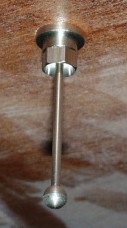
The antenna itself is just the little 2.5" long stub that came with the Terra TR-250D that I'll cover with a foam and fiberglass fairing next time the fuselage is upside down.
Once the radio was in place, I spent several days researching and scratching my head over where to locate the Kuntzleman Dual Doubleflash strobe box. My gut feeling was to put it out in the wingtip where it would cause the least interference. One of the things I learned is that it's vital to ground all of the radio and audio components to exactly the same place as the strobes. This doesn't seem intuitive, but the theory is that if they are grounded at different places, an electrical potential can develop between the grounding points, creating radio noise. The strobe case should be grounded to this same place with a dedicated 16 AWG wire. It's also important to use a shielded twisted pair of wires for the power leads, with only one end of the shield grounded. The shield is always only grounded on one end, for the same reason as before, to prevent any potential difference in the two ends of the shield, and thus a noise producing current flow.
But I eventually settled on a location behind the seat, equidistant from the antenna in the rear, and the transceiver in the panel, and on the opposite side of the fuselage from the antenna coax. I installed the power supply, ran the wires, soldered and shrink wrapped the terminals, grounded the case with the dedicated wire, etc, and made a nice neat installation. Then I temporarily wired up the strobe heads (the wings are not attached, you know) and turned it on. JEEEZE, you would not believe the noise! A very loud hissing noise came out of the radio between flashes that was TWICE as loud as the background noise! I assume this noise was EMI from the capacitors charging or something, as it was unrelated to the actual flashes.
Well it was bedtime so I called it quits for the day. The next day I completely isolated the power system, by providing a battery about 6 inches from the power supply, independent of the rest of the plane's system. The interference was unchanges. This clinched my theory that the problem was not related to grounding or other power supply glitches. RFI was the culprit.
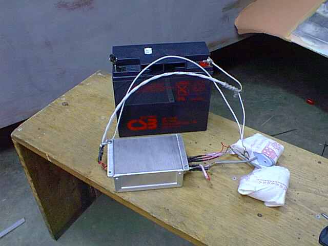
Next I created "strobes in a box", a box containing battery, power supply, and both flash heads (wrapped in power towels to keep from scratching them, and blinding me). I walked around the plane with this box of RFI snakes. Generally if I was within 6 feet of either then antenna or receiver, I had noise. When I set the box on the end of the stub wing, it was dead silent. I could put on the headphones, close my eyes, and couldn't tell you if the strobes were on or off to save my life!
Having learned from my previous experience, a prototype installation was next. I temporarily ran the shielded 16 AWG twisted pair wire from panel to power supply, at the approximate location of where the wing tip should be, along with the dedicated 16 AWG case ground wire. One flash head was connected right to the power supply, and the other was run across the fuselage to the other "wing tip" using a shielded twisted bundle of 5 22 AWG conductors. You can get this stuff at any large electronics store. You only need 3 for the strobes, but I also ran 2 for the nav lights. This wire is already installed inside my wing's leading edges, so I had to dig up some more for the test.
Once the test proved that the noise was history, I used 9 pin Molex connectors between stub wing and outer wing for a quick disconnect. 3 pins for the strobes, 2 for strobe power leads, 1 for strobe case ground, 2 for nav lights, and one to continue the outer braided shield from one cable to the next. The 5 conductor shielded flash head cable runs into the cockpit at the leading edge of the wing, along the front of the spar (down low) and out to the other wing leading edge. I think this is the ticket.
I should mention that having seen the Kuntzlemann strobes in action, I'm not completely impressed. The strobes' flash rate is not what I'd like, consisting of a total of 66 flashes per minutes, which is slightly more than a double flash about every two seconds on each wing. I don't really think that's enough for safe visibilty, and will probably buy an Aeroflash powersupply to run the strobe heads that I have at about twice the rate.
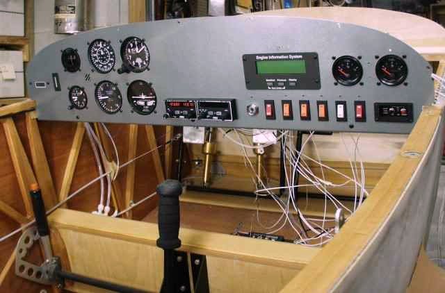
Here's the final panel, complete with Carlingswitch breaker/switches and EIS. All that's left is the GPS, which I probably won't buy until my 40 "proving" hours are flown off...
Return to Mark Langford's KR2S Construction.